
Contact: Rich Kurz Page content last updated July 29, 2026
The Construction Diary
2026
JANUARY
Take a deep breathe and let's wrap this up!
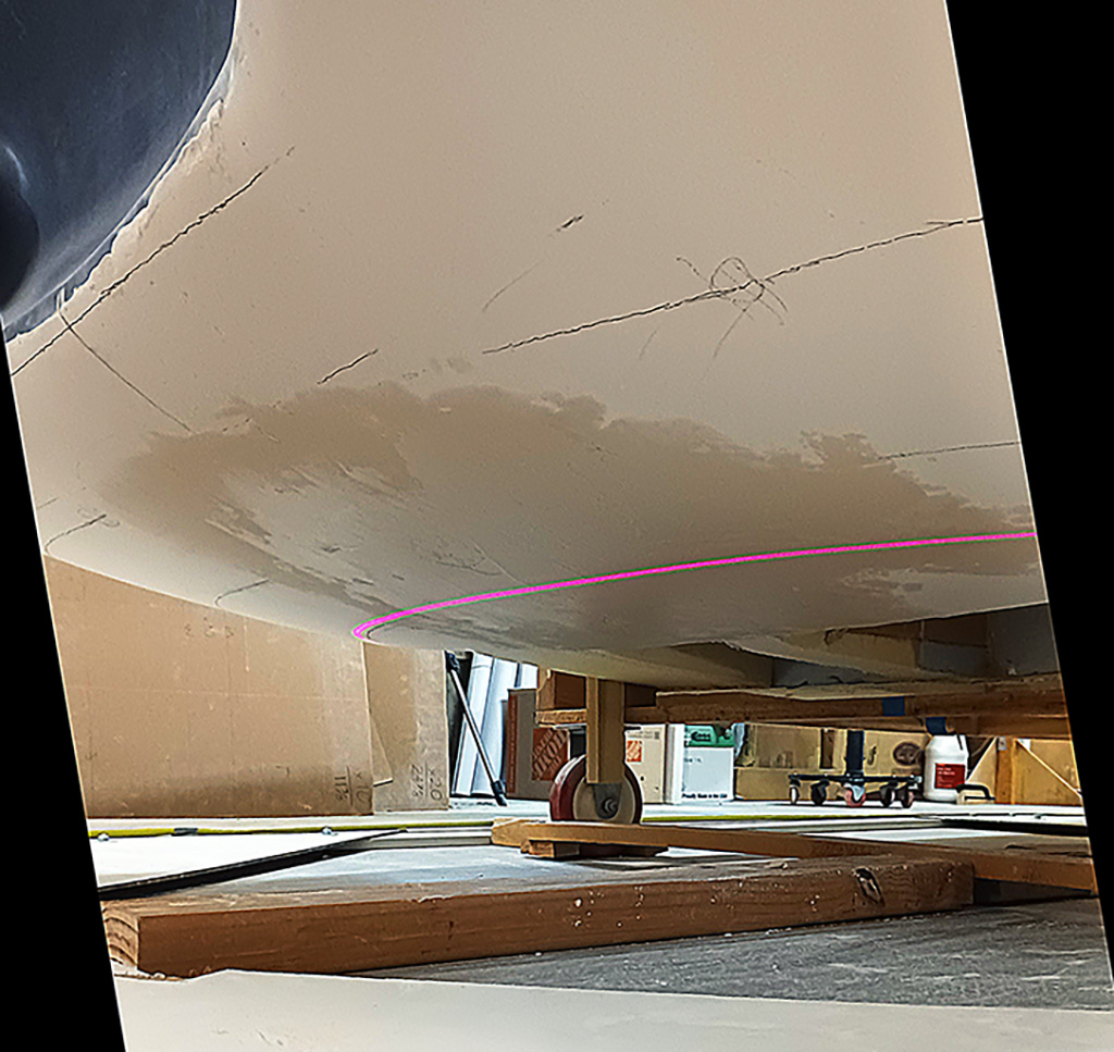
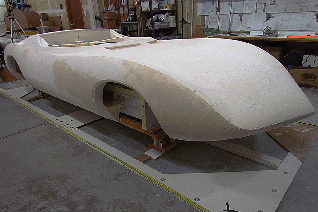
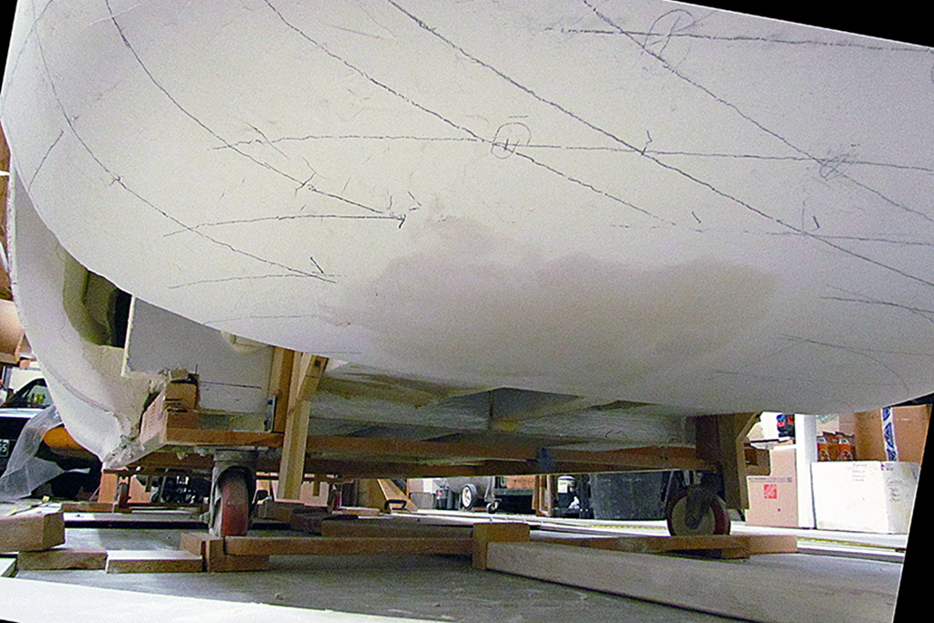
The rear underpan is a good place to start.
I left it only roughed out. Now to finish shaping it and making it symmetrical left & right.
I create a couple of contours from my 3D file for four locations.
Studying the photos, it seems the kamm center section sets the basic shape from tail to rear wheels, and the kamm wings blend into it.
I sand to the center shape and bit by bit shape the outer kamm wings to blend into it.
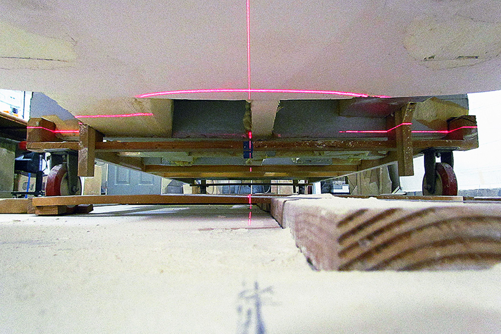
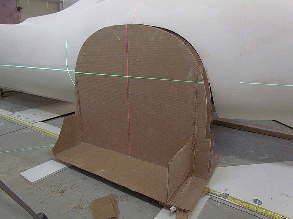
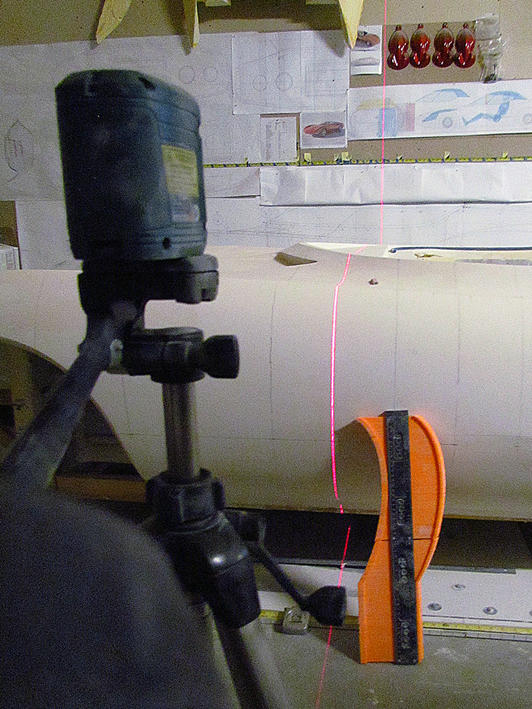
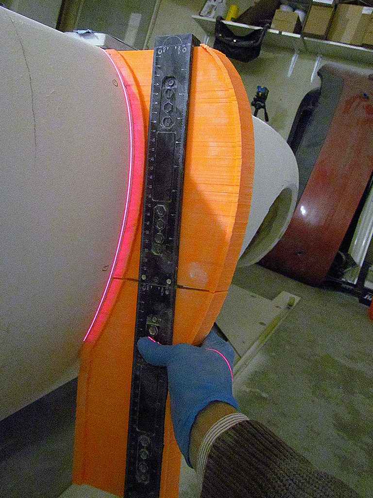
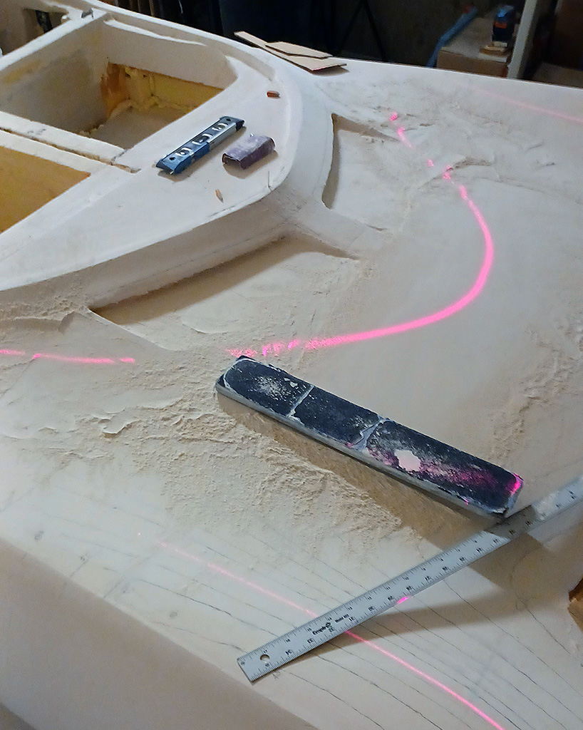
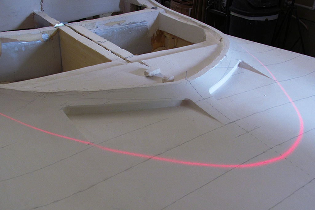
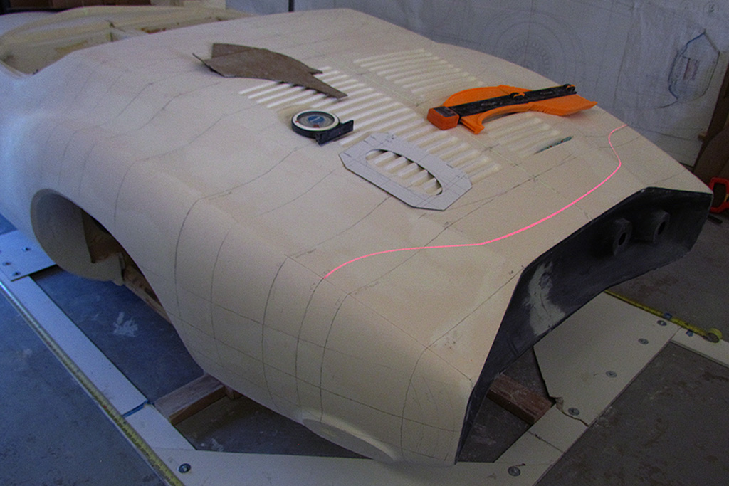
With the basic shape established, I cast horizontal laser lines across from behind and at different heights.
I simply keep shaping until the curve of the laser lines look equal left and right.
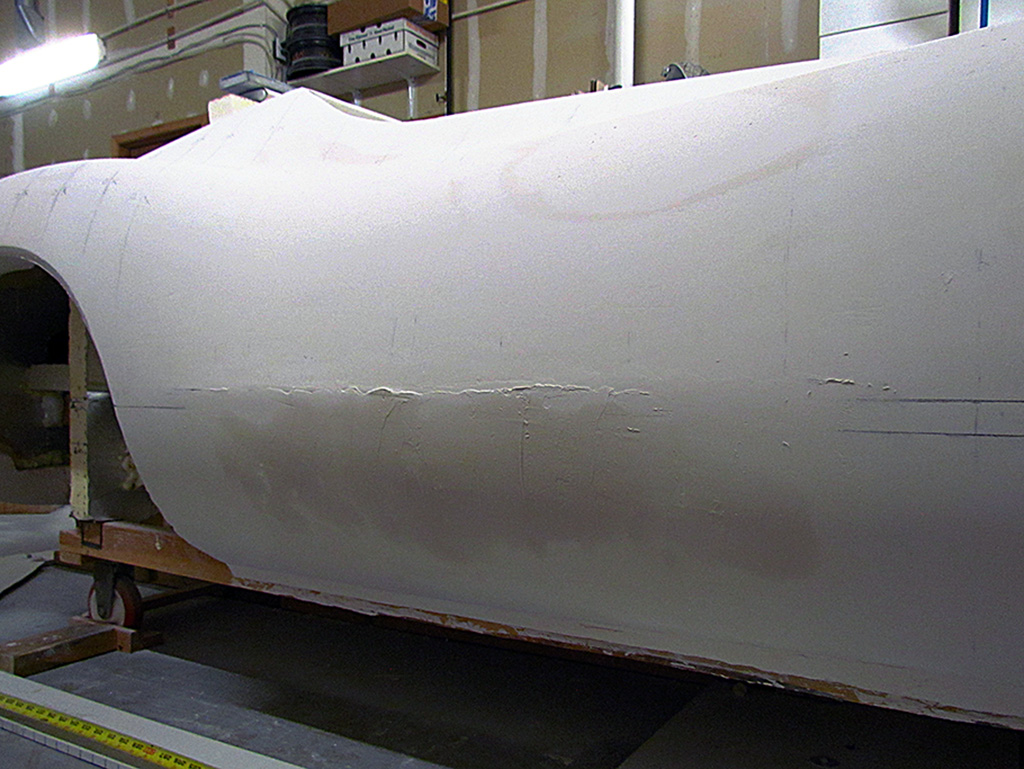
Then I fill in the pits and pinholes.
One last set of checkes to make sure the lower profile of the rear fender matches left and right.
The right (passenger) side needed shaping adjustment.
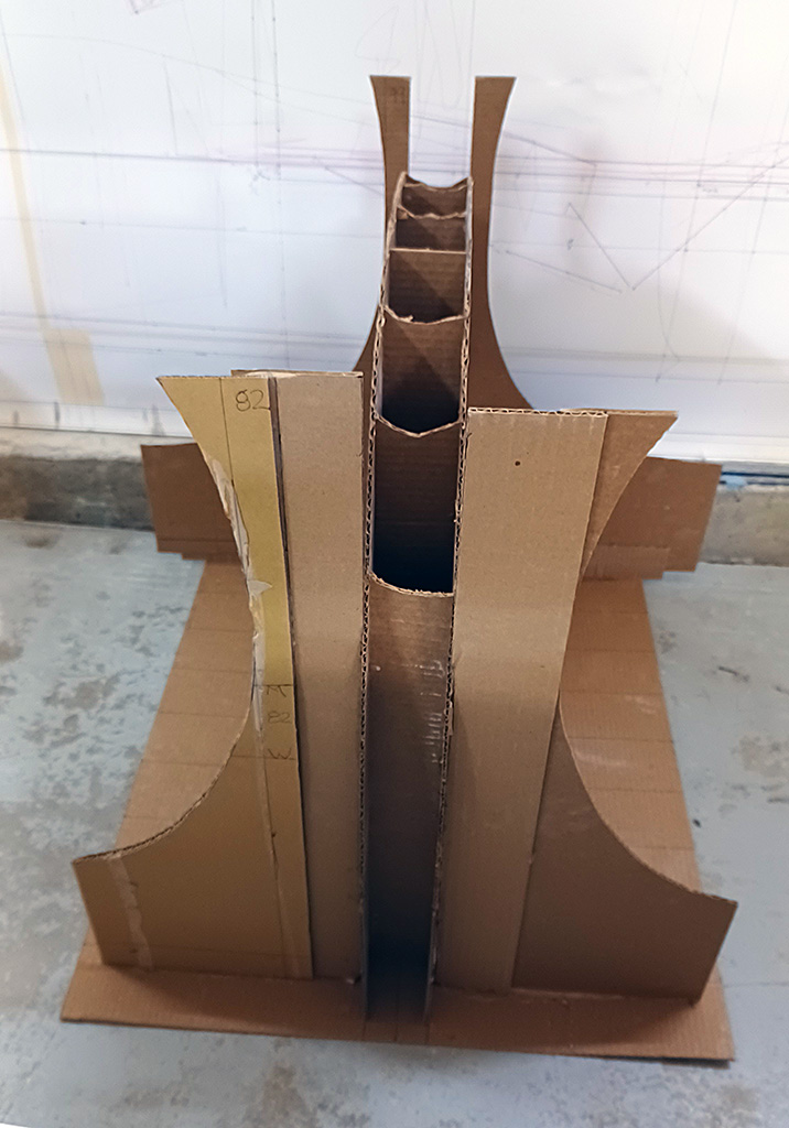
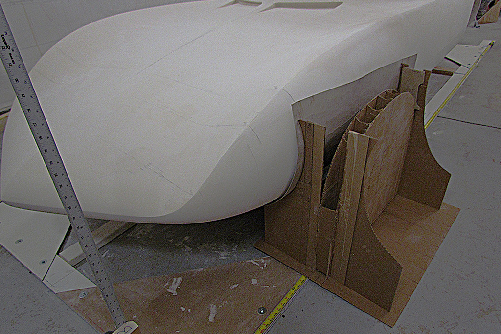
Next I begin making my pattern for the wheel wells.
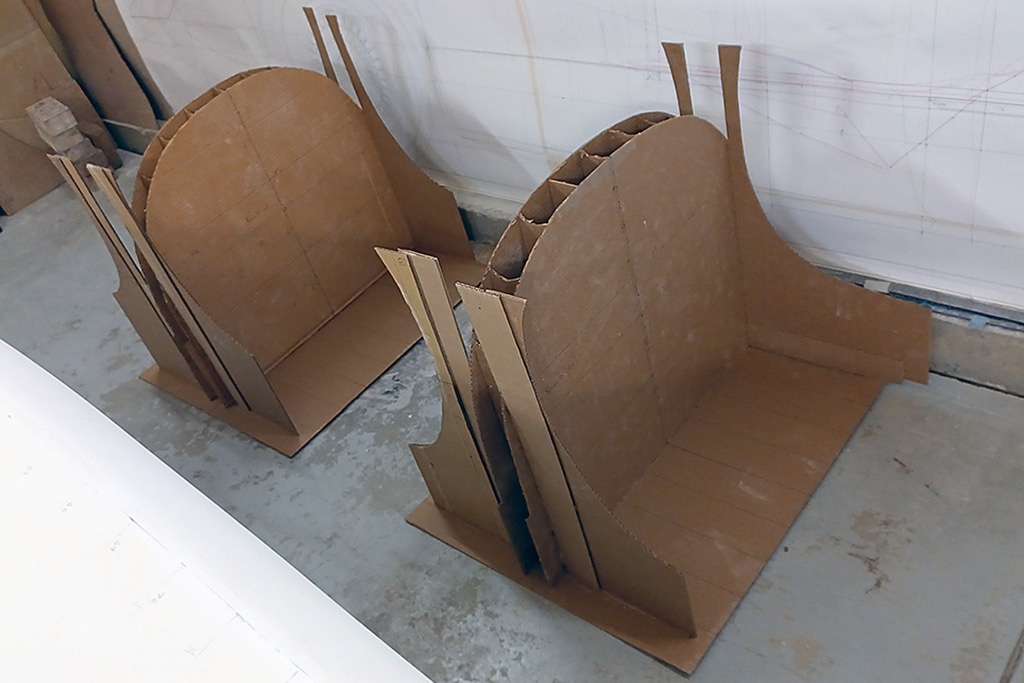
I start by pinning the outlines for the front and rear wells onto two sheets for each set of wells, left and right for front and rear.
The photos show my approach.
What I want to do is use the patterns to trace the opening for each well.
Since each well changes in depth, I plan on using a cardboard sheet to curve like the body and use the patterns to cut out the opening (see 2nd ROW, CR image).
Great theory, but the cardboard is too flimsy and the whole idea is really just overkill.
I scrap the sheets and use an old drafting pencil lead and trace the outline using just the patterns (see 2nd ROW, R image).
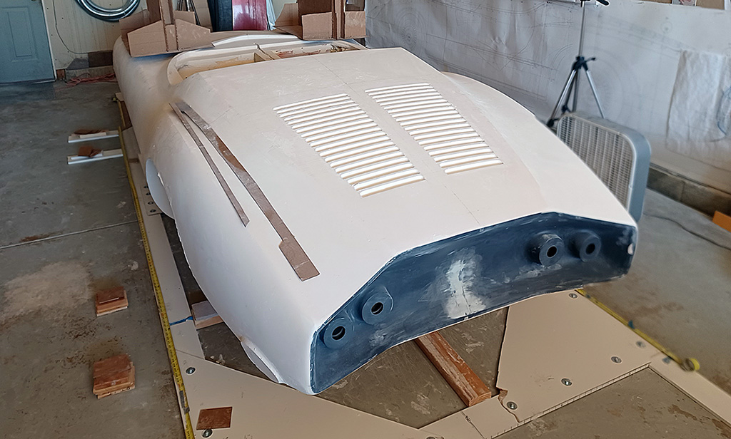
Since drying time is involved with glueing the patterns up, I also keep working on the intakes.
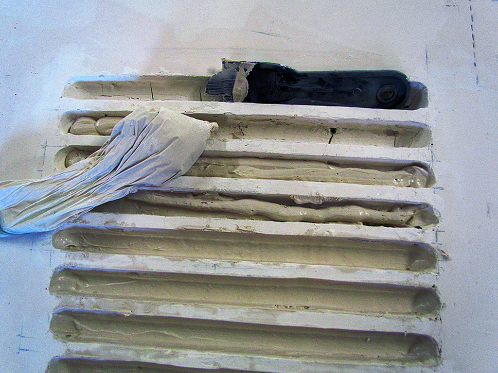
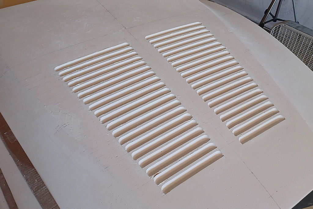
After building up the strakes, the vacformed inserts ended up too deeply recessed, so I tried squirting in plaster and shaping it with a contour I cut out of putty knife.
That did not work real well in practice, so I ripped out all the vacformed louvres and filled the hole with plaster and used the putty knife to get a roughly shaped recess.
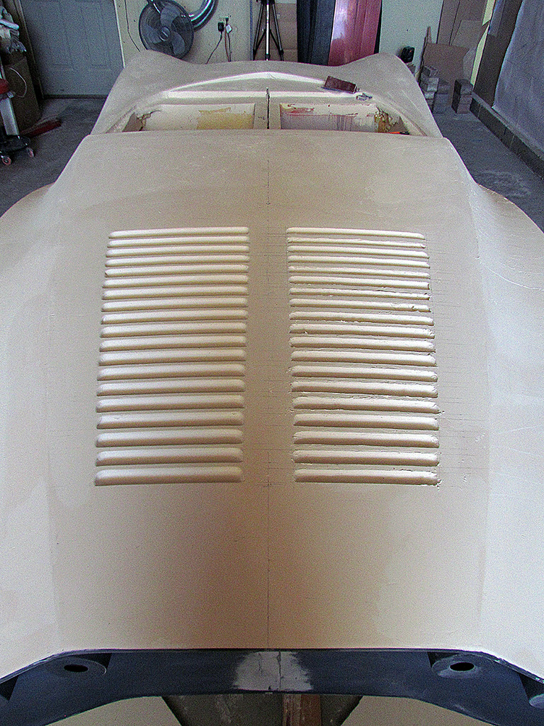
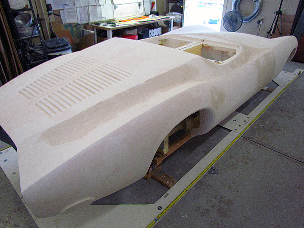
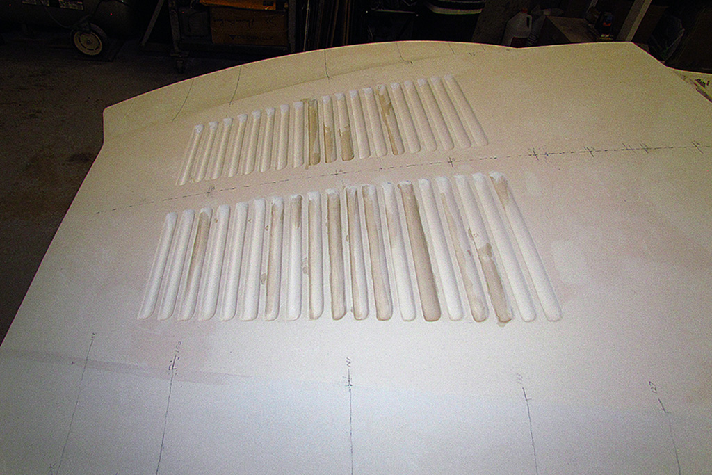
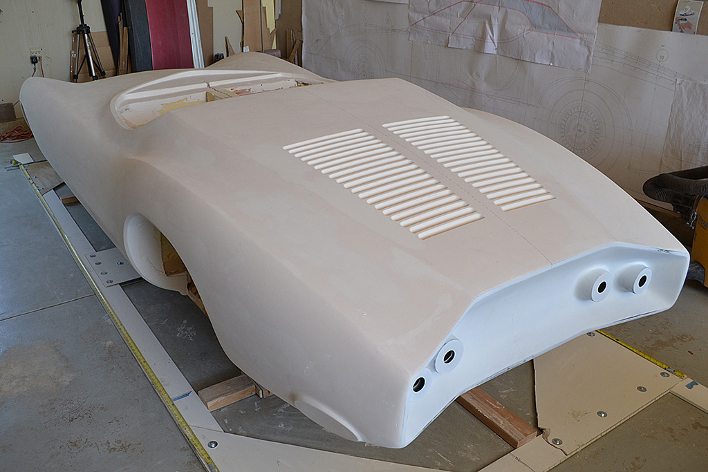
The Dremel was too unforgiving if it slipped or varied at all, so I was reduced to hand-sanding every louvre - all 38 of 'em.
FEBRUARY
Hand-sanding the louvres took a couple of afternoons - not as long as I thought.
And the results were impressively good... from a distance of 5 feet.
If you study them, you realize that the widths of the strakes sometimes varies noticeably.
Some are unacceptably too thin and must be beefed up.
This will be on ongoing process while I work on other parts.
It is at this point that I return to the wheel wells.
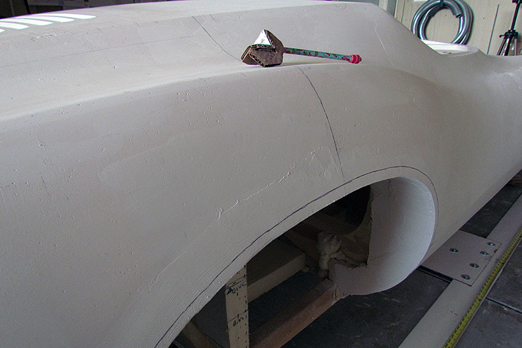
I was not thinking correctly when making my patterns, and made them to outline the outer edge of the bevel around the wells.
It really should have been the well cutout instead.
I decide to make it work instead of making new patterns.
So I make a pencil guide of 1/2 inch and trace the desired cutout, adding plaster where needed.
Then I sand the well opening final shape.
Then I make another pattern to check my bezel width as I sand that into the well outline.
It is actually not a half-inch when viewed orthographically, but a half-inch width bevel.
Because of the fender curvature, there is a slight variance along the well opening.
Plaster - sand, plaster - sand, eventually it is done.
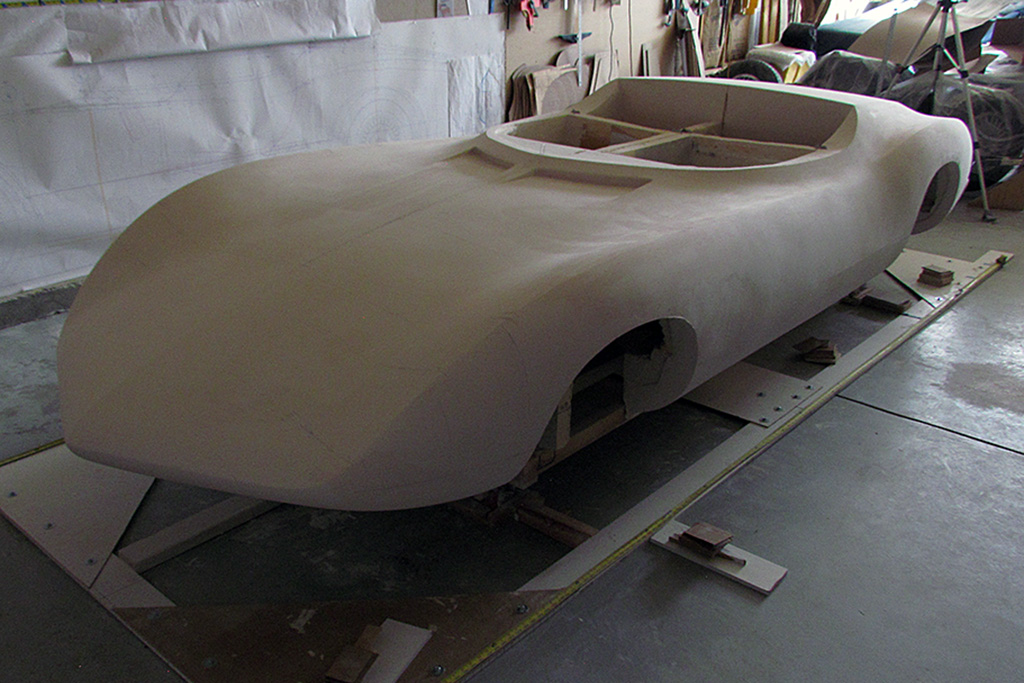
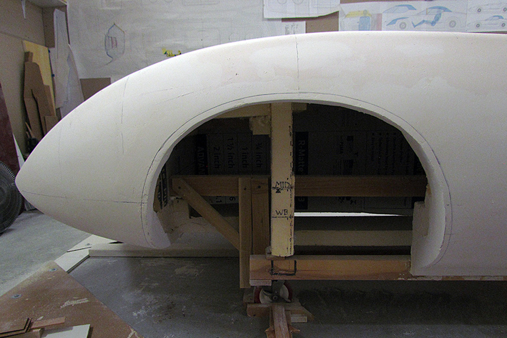
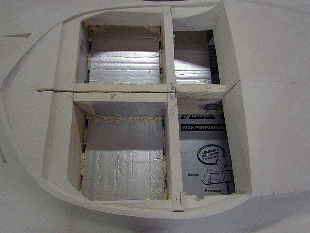
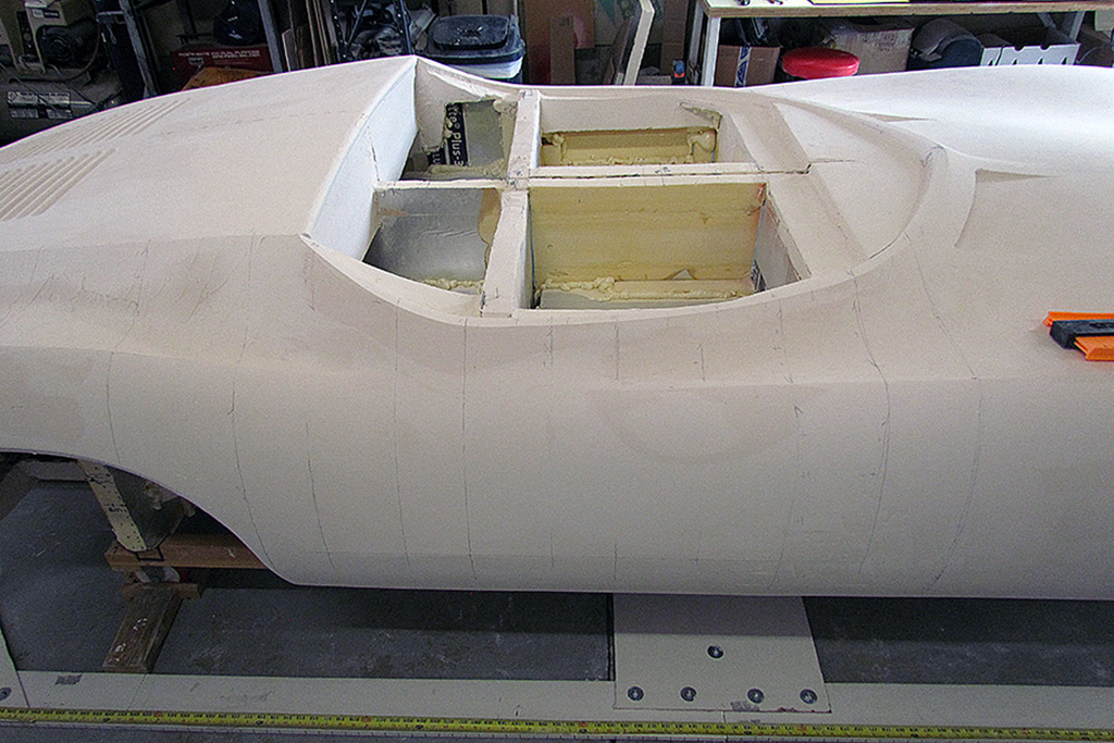
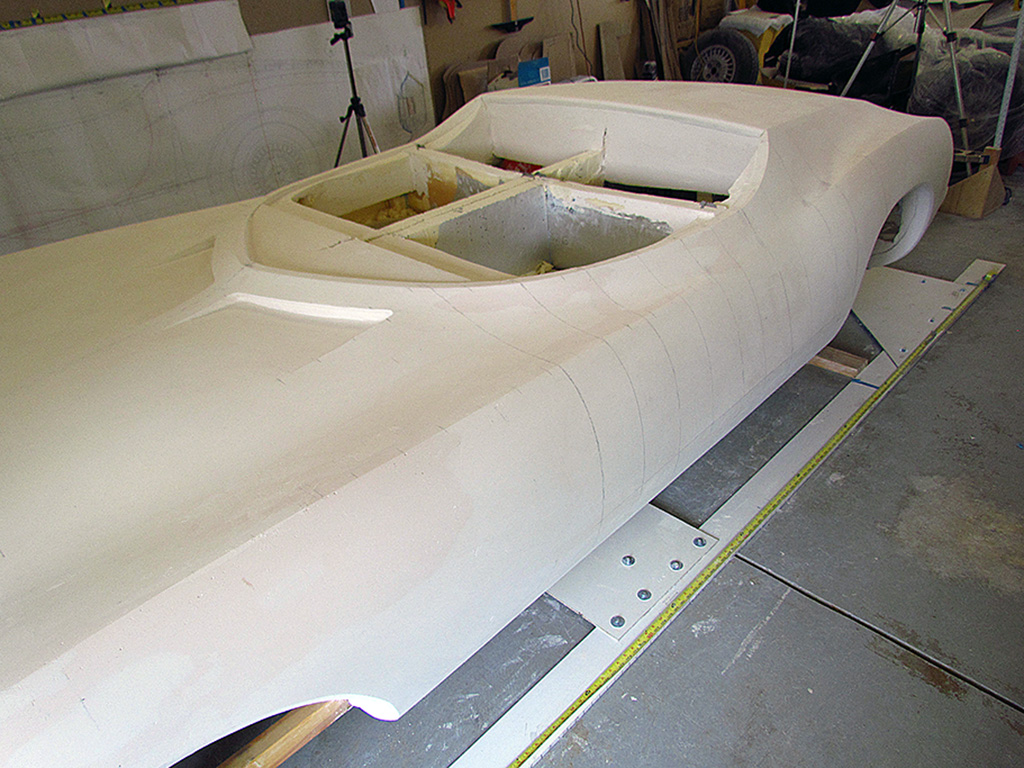
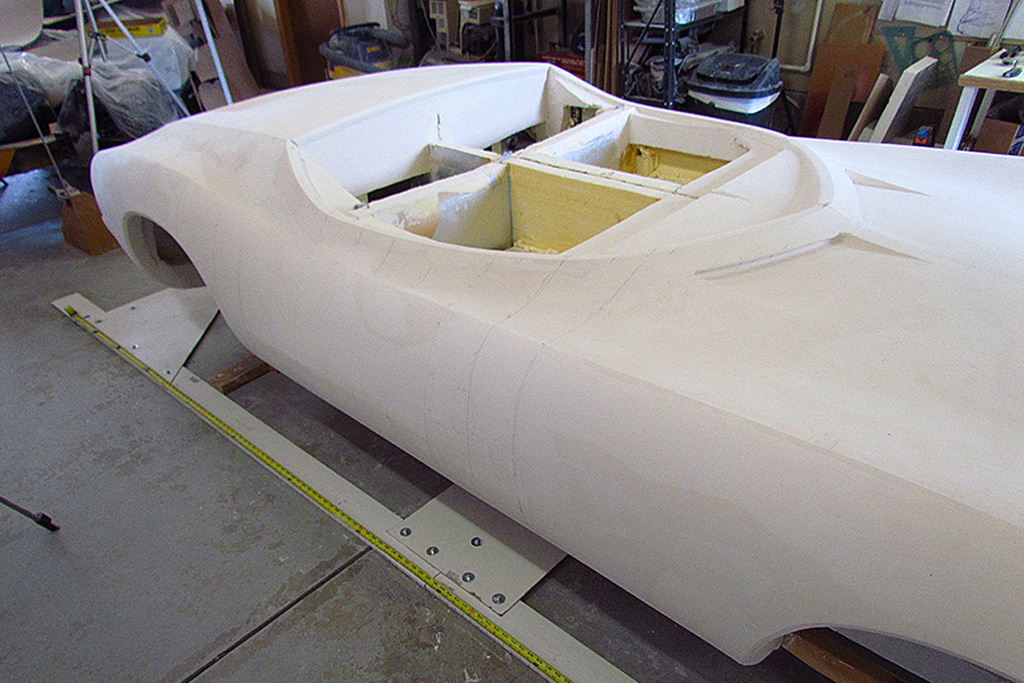
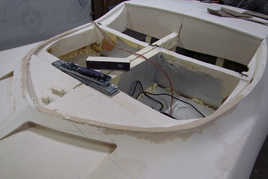
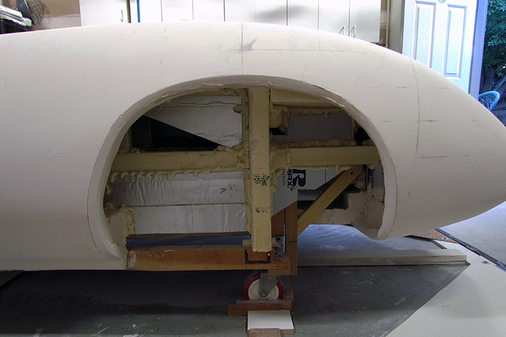
At this point, I step back and decide NOW is the time to add the internal reinforcements to strengthen the body for moving.
I'd rather repair things now before I finalize the surfaces.
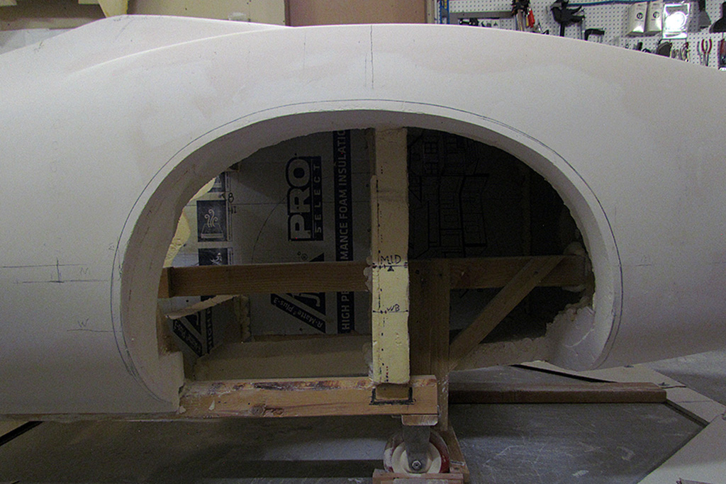
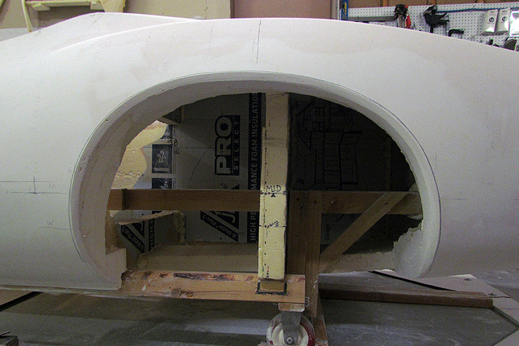
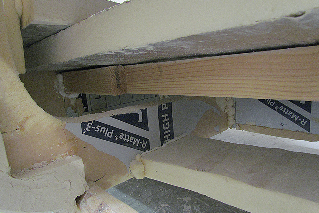
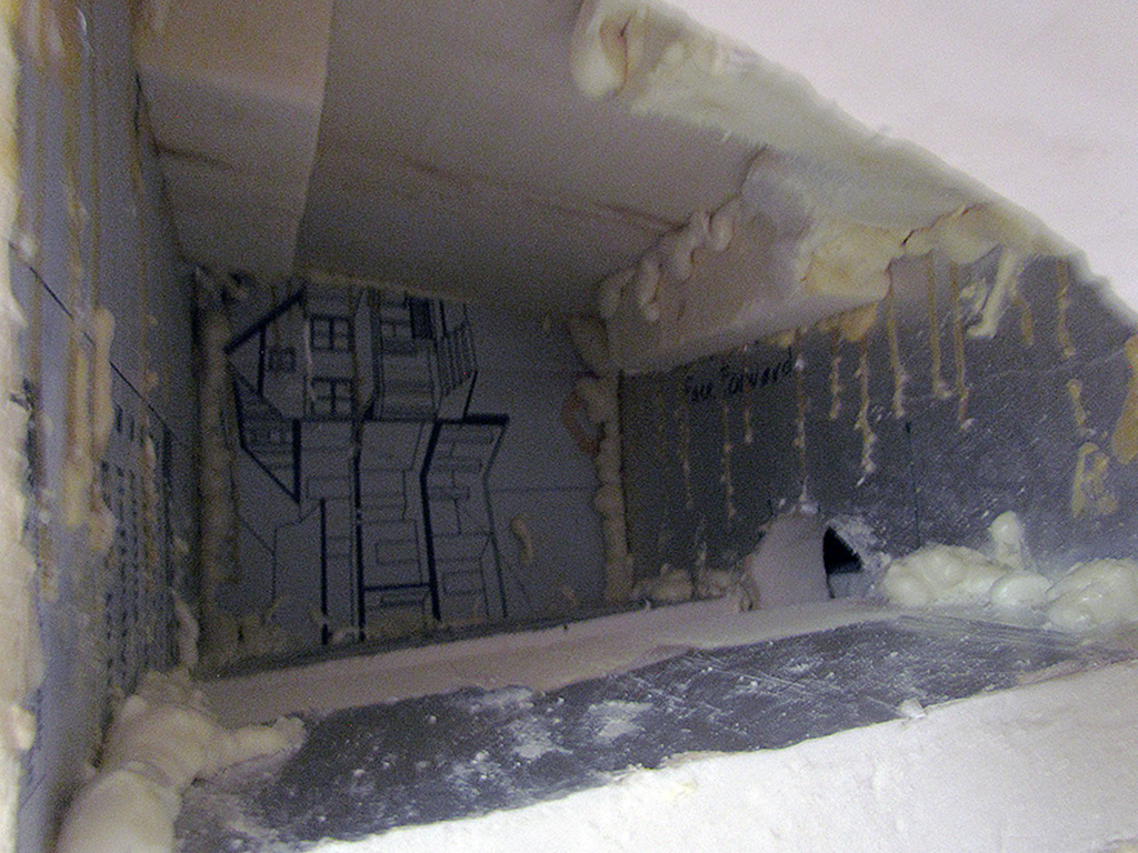
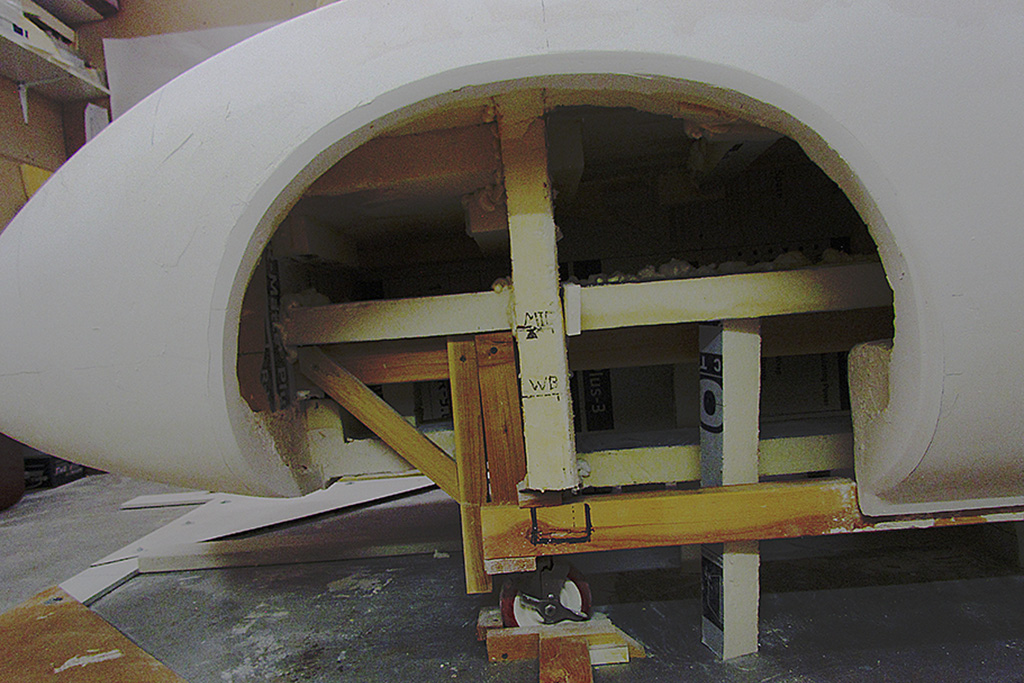
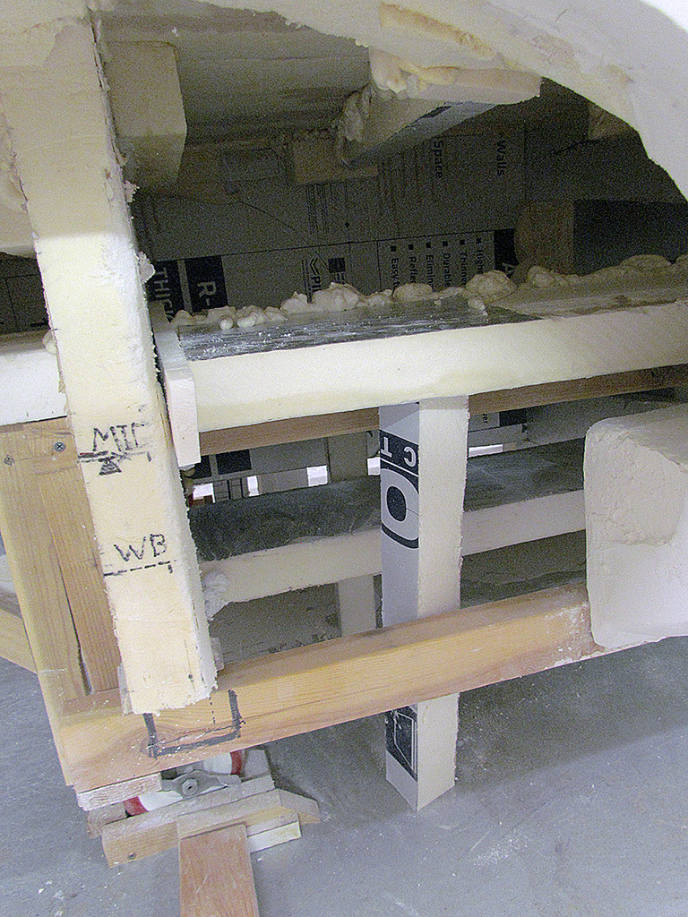
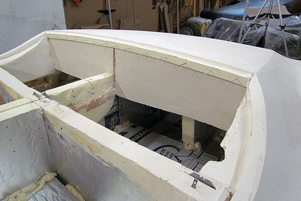
The photos show the basic problem.
I have a center sheet of foam and a dozen contours at right angles to it, plus some pieces I insert along the bottom.
I imagine lifting the possibly 400 lb. body at the wheels and ask myself, 'where and how will this bend or droop?'
Answer: It will droop from the lifting points downward.
That foam can't handle much weight.
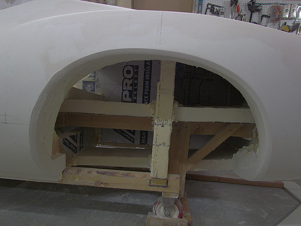
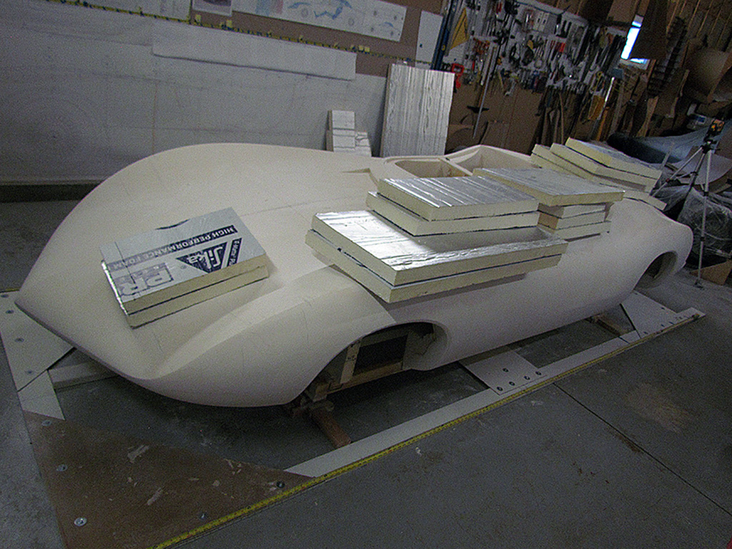
Solution: Add foam slabs in each cell on each side to add rigidity.
The four cells in the cabin area have a double thickness of slabs.
It is very rigid, but I also need slabs thruout, front to back, to maintain rigidity.
Keep in mind that at the core are now a pair of 2x3 studs made of two 2x3 studs that overlap by 4 feet.
They will carry all the weight.
I did not glue the body to them, but it rests on them.
The slabs are meant to keep the body rigid - not to be the lifting points.
MARCH
It strikes me that the front lip of the rear deck where it meets the seats does not end as a sharply creased edge, but with a quarter-round lip.
I calculate it is about half an inch.
So I lay out a strip of foam and begin building it up in plaster.
I begin addressing final details, such as the shape of the exhaust exits and the passenger door crease.
And continue working on the louvres, again and again and again, but fewer each time.
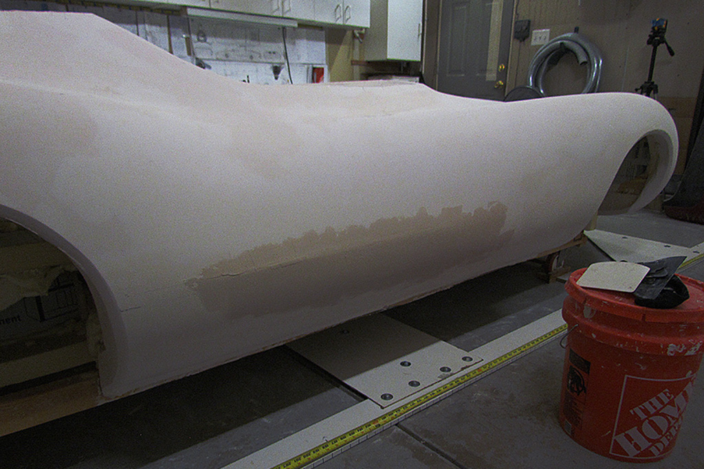
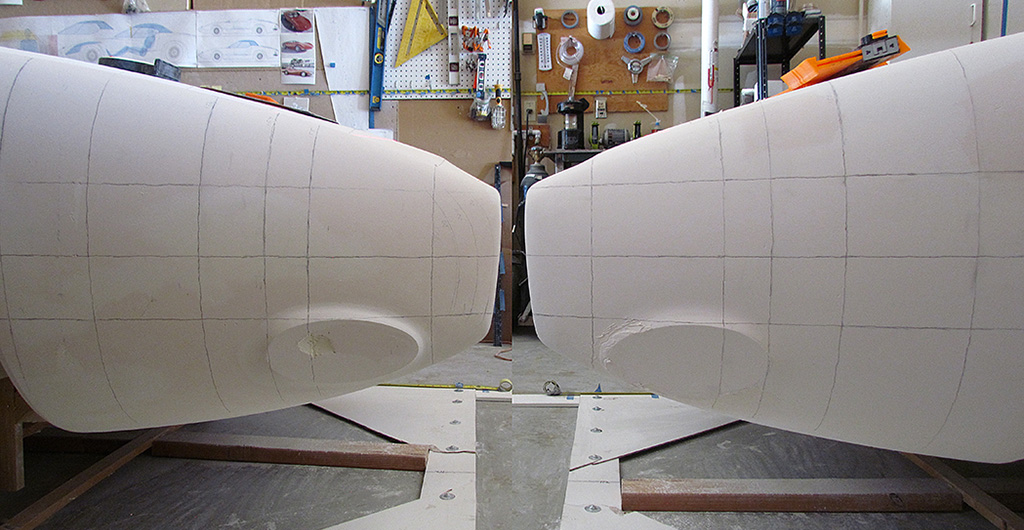
And I begin addressing the symmetry of the passenger side to the driver side, the side that is my master.
For no particular reason, I just happen to start working from the rear to the front.
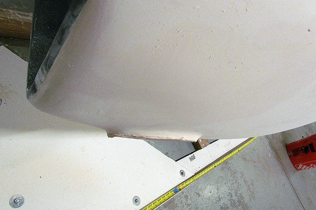
Another area that finally gets addressed is the top surface of the rear fenders.
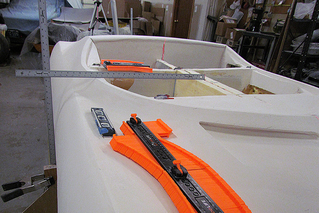
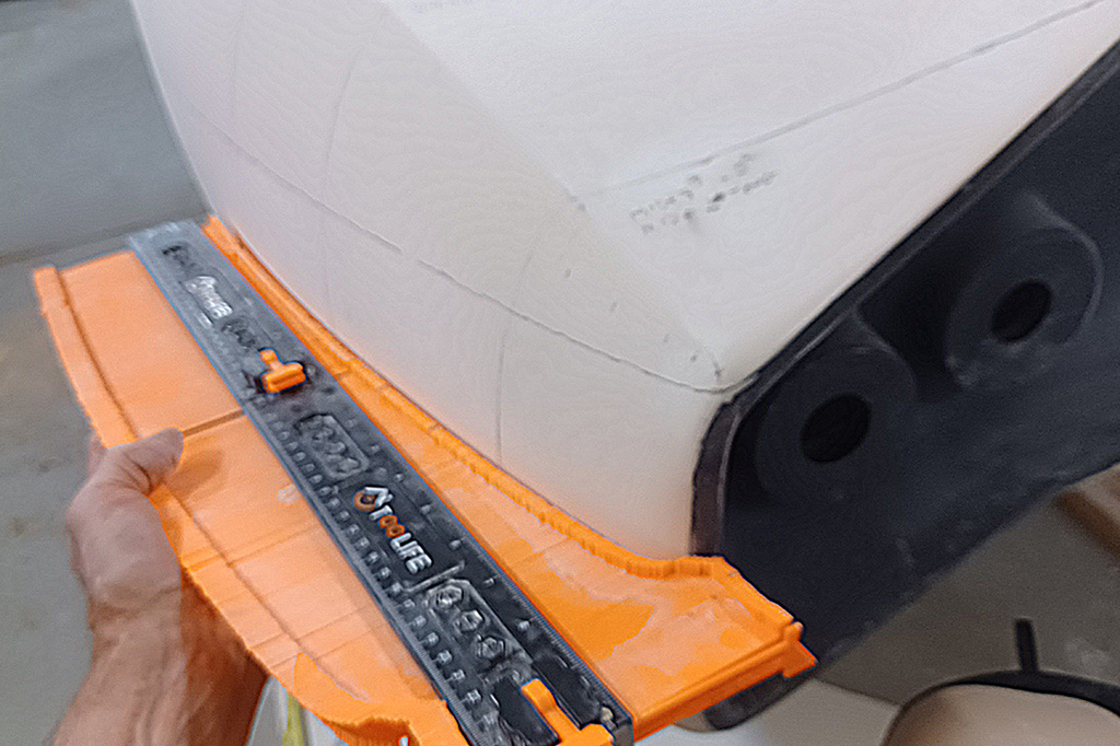
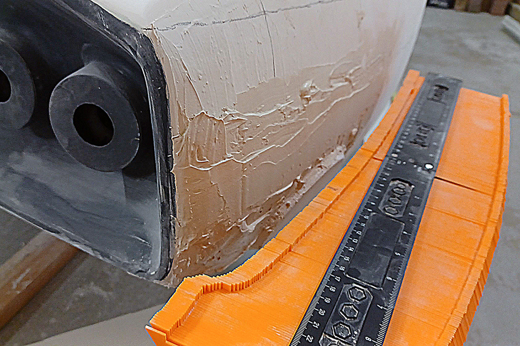
As with the car overall, what looks good turns out to be off when checked with a contour guide.
I ordered online a set of guides.
They are made of plastic and are not the easiest to tighten down a contour once made, but they can be attached end-to-end to get a longer line.
BTW, I also start with a hard measurement of the width from the centerline of the body at differnt points along the length.
The passenger side did need to be made wider and fuller in places.
This becomes an iterative process: draw contour section lines on both sides in pencil;
take contour of driver side and check the passenger side;
sand down high spots and plaster up low sections; repeat as needed.
APRIL
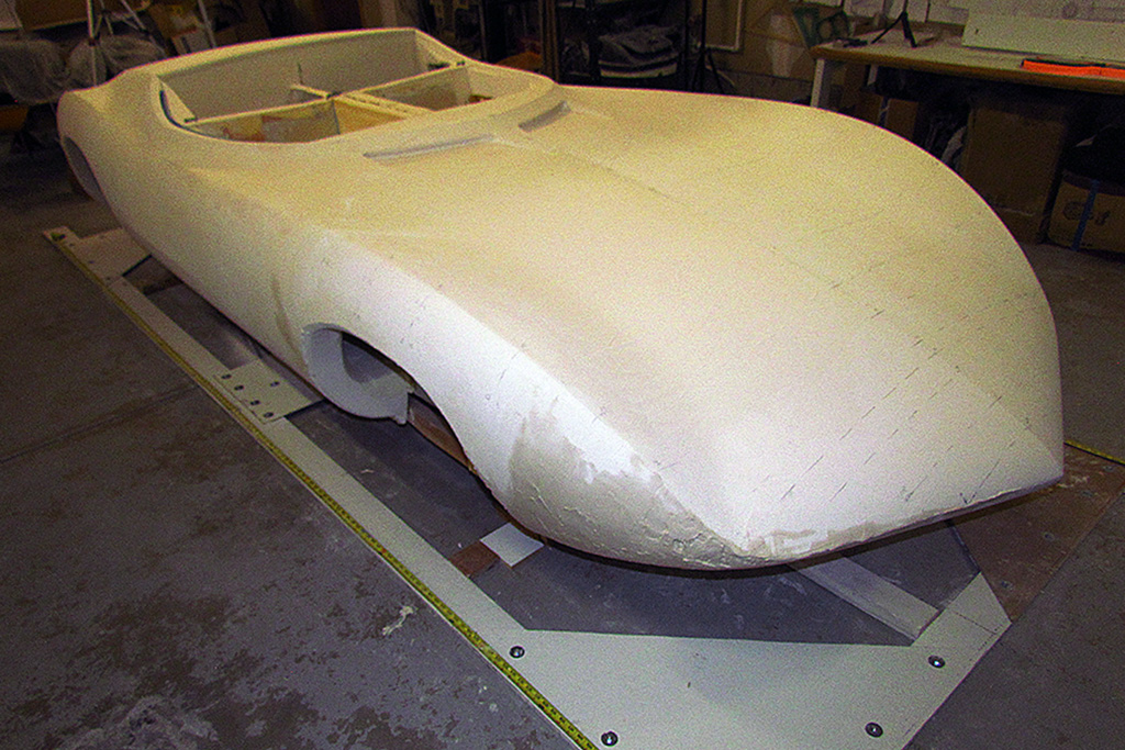
By April the shaping is good up to the front cut line of the door.
All the ridge lines had to be reestablished.
When I stepped back and viewed it from the rear, both sides did indeed look symmetrical!
It is coming together.
Those pesky louvres still need touchup, the strake widths do look much more even.
I did a laser contour check of the rear deck, which has suffered a lot of touchup the last few months, and found it held true.
Whew.
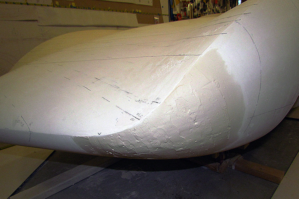
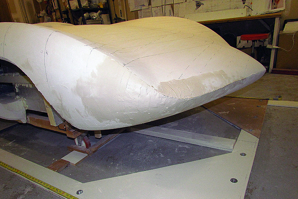
Moving forward, from the door to the front wheel well, the side needed to be made fuller and the fender ridge moved out about 1/4 inch.
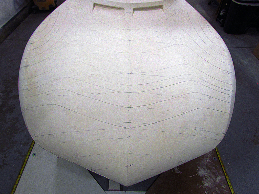
The nose needed the most work.
I decided neither side was quite accurate, so both sides are being made fuller.
The passenger side is especially off and needs a lot of build-up.
And while plaster dries, I cast laser lines on the hood.
The passenger side needs minor sanding down and plastering up, but it shapes up nicely.
The end of the right rear fender continues to defy matching contours.
In a fit of frustration, I create a new set of vertical profiles and then sand down past what I think it should be.
The exhaust port now stands out like an island in the middle of a lake in the middle of a drought.
That's going to be a lot of plaster to build this back up.
Start splattering.
MAY
At this point I am working all around the body as my eye catches curves that look too flat or uneven.
The rear fender progresses over a week and the contour guides begin to match.
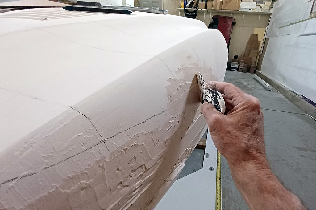
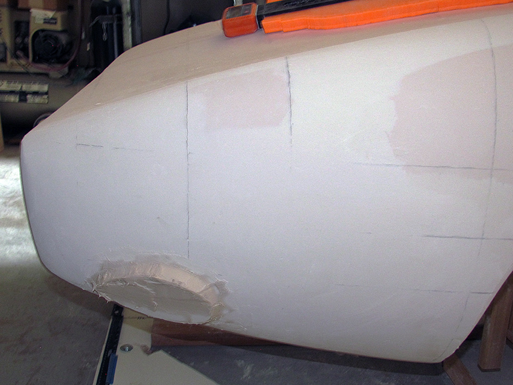
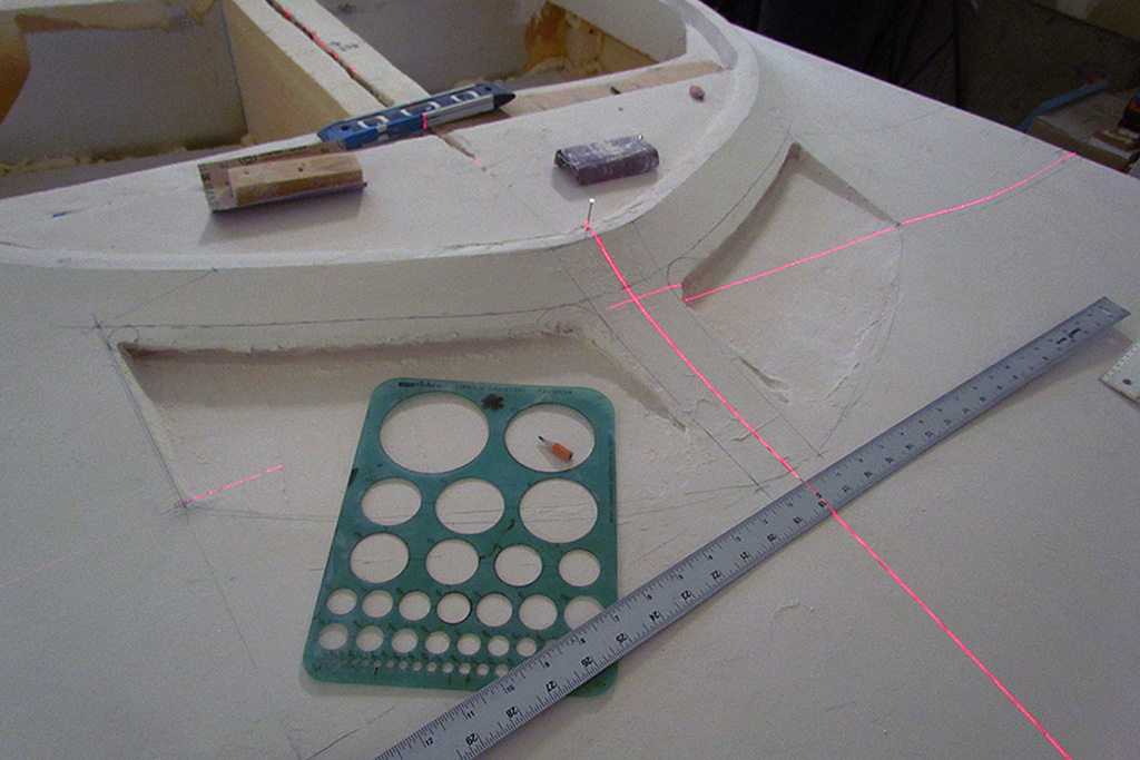
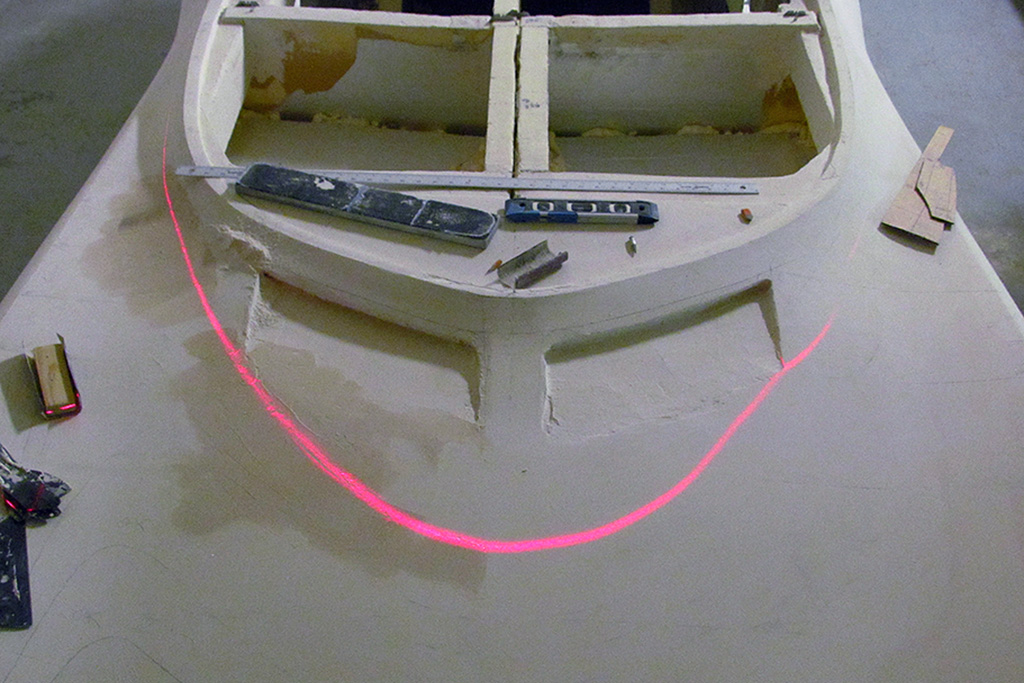
As the pictures show I touch up around the front vents, the door ridge, and front underpan.
Finally the rear fender gets close and is in the range of doing touchups.
The rear exhaust port can get resculpted, and slightly nudged up to better match the driver side.
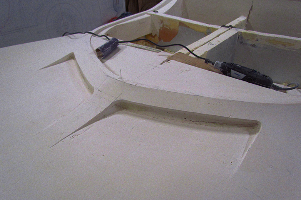
The big surprise is realizing that the front intakes come too far forward.
I think I mistook the distance from the front lip to the top of the painted band on the windscreen as the actual length.
That would not be. I should have been measured only to the line where the windscreen meets the body.
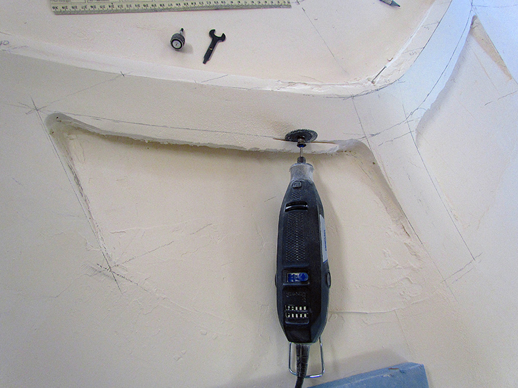
Dig out the Dremel cutting disc and recarve that whole area.
In the end, yes, it does look correct and works better with the shovel area in front of them in terms of where the flat shovel surface begins.
Yay.
And while I am at it, the horizontal laser line reveals a contour problem in that area.
Fixing it goes quicker with the laser continually shining as I add and shape the plaster.
That is how it is suppose to work!
JUNE
As these touchups slowly get completed, I begin checking the bevels around the wheel wells.
The front driver side bevel especially needs reworking.
My measurements indicated the entire opening needed to slightly shift forward, which meant adding plaster and redoing the curve.
And doing a lot of rechecking for positioning.
It, too, gets completed.
Trying to work ahead of myself, I cover the body and place the rooftop pattern back on.
I check it for fit where it meets the cabin outline and for curvature smoothness on the driver side, my master side.
I add plaster around the cabin outline to better match the contour.
And then I begin shaping the passenger side to match.
It is still a rough, but it may be usable to make the surface mold of the windscreen and side glazing.
Or it might all have to wait until the fiberglass body comes back.
Finally my walkarounds have me going in circles trying to find anything that still needs attention.
I can't really. . . that could only mean . . . I am ready for the last step!!!
JULY
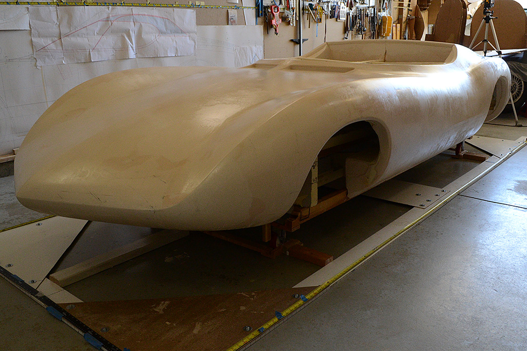
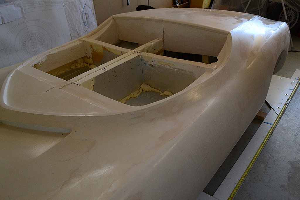
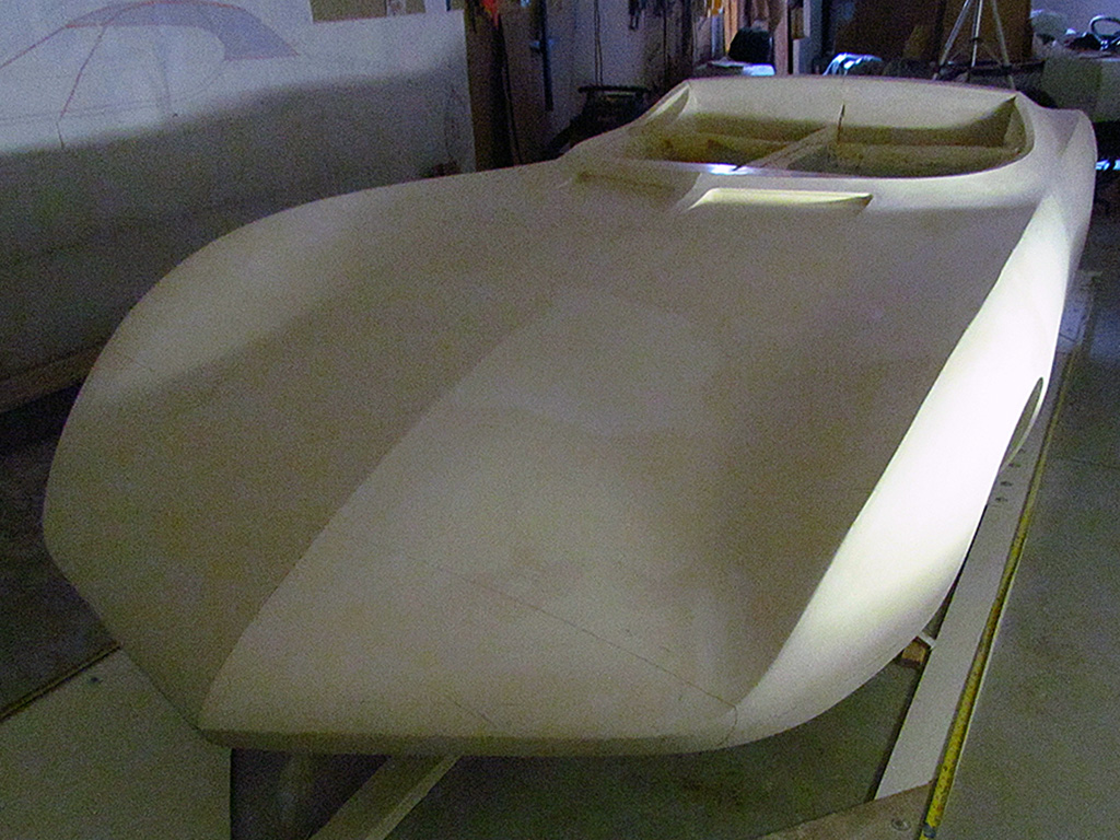
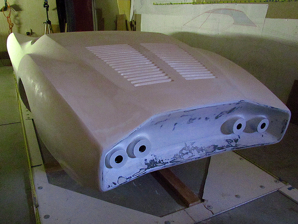
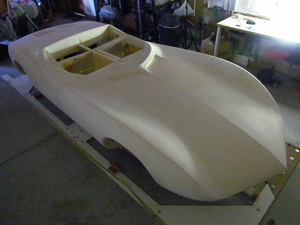
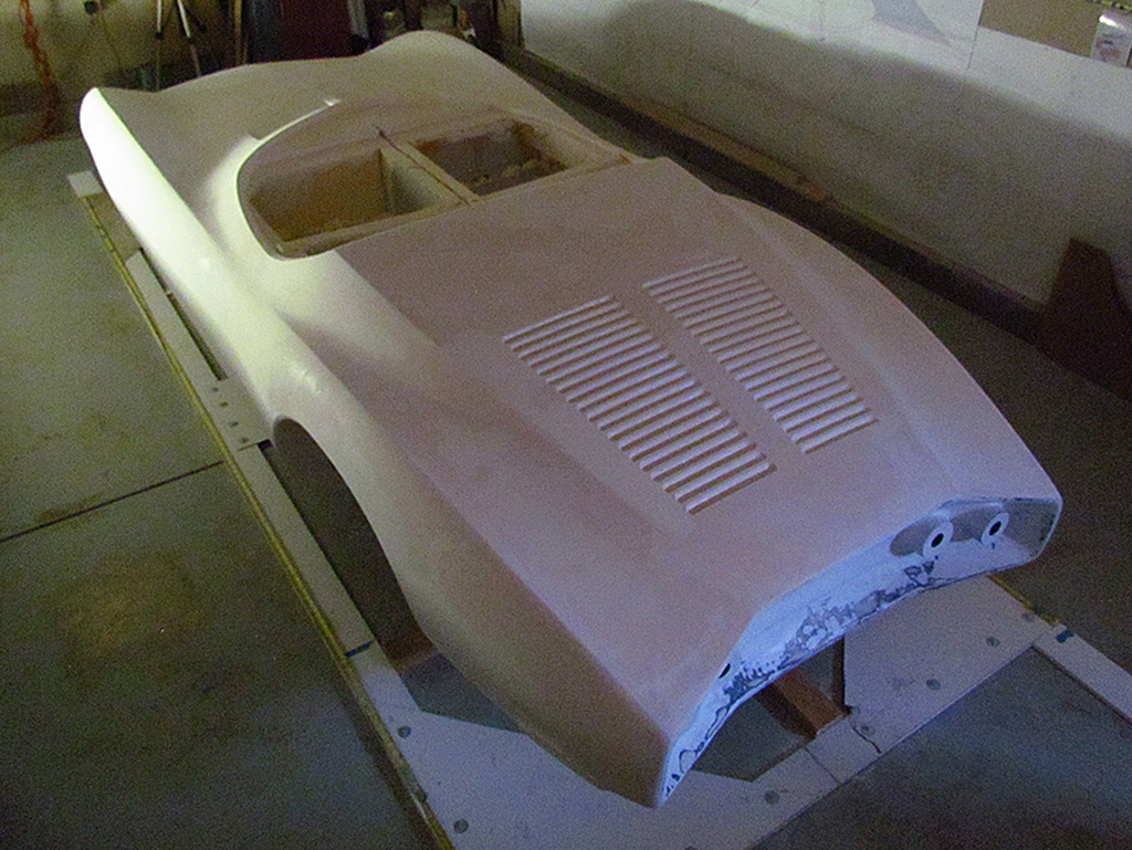
It is hard to believe, but I may be ready to do the final step - the surface hardening.
I have been waiting nearly a year to do this.
I learned about this product from a local sculpture supply store.
The sculptors use this to put a finish on plaster sculptures before sending them off for casting.
All I had to do was pour it into a spray bottle and apply!
Except...
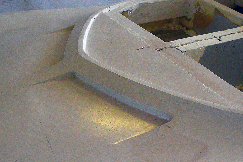
It does work, but it is hard to control the application.
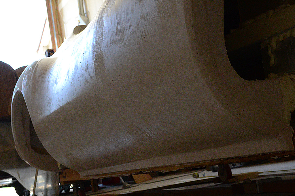
It is very viscous and runs very easily, very quickly.
So it does not dry evenly and runs dry in place.
I just learned that I should have used a spray gun on something else first.
But I did not.
So I need to start sanding it smooth again.
Only this time I have to be careful going from a hard surface to a soft one.
I then had to skim more plaster on to correct divots and unevenness.
That adds up to about a week.
Meanwhile I had called the fiberglasser to arrange a pickup.
Happily the date was set two weeks out.
That gives me time to do fixes.
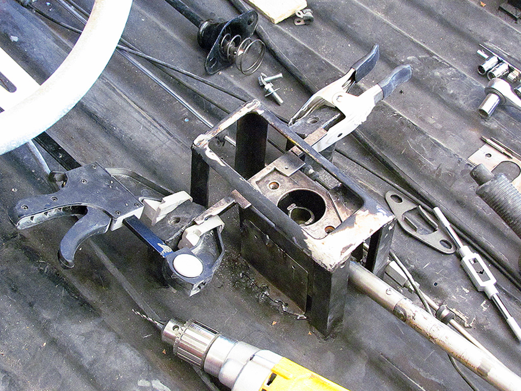
I also begin working on the shifter so I can move the chassis out and back in under its own power.
I observe that the shifter box wiggles back and forth when working the gears - searching for the gears.
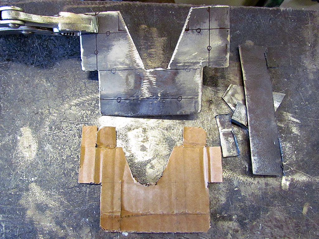
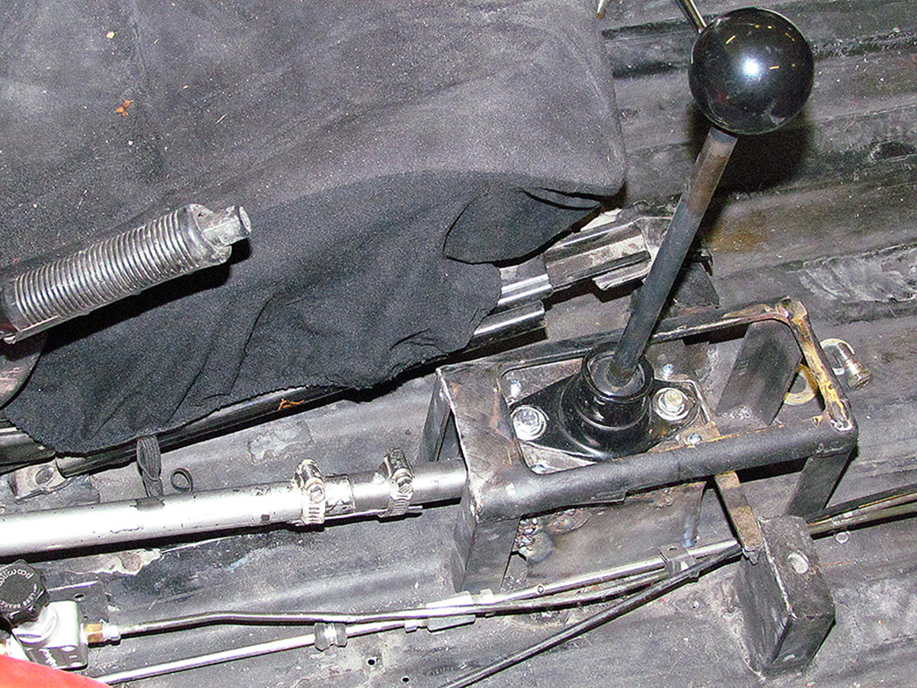
I fashion two brackets to hold it down, on the front and the back.
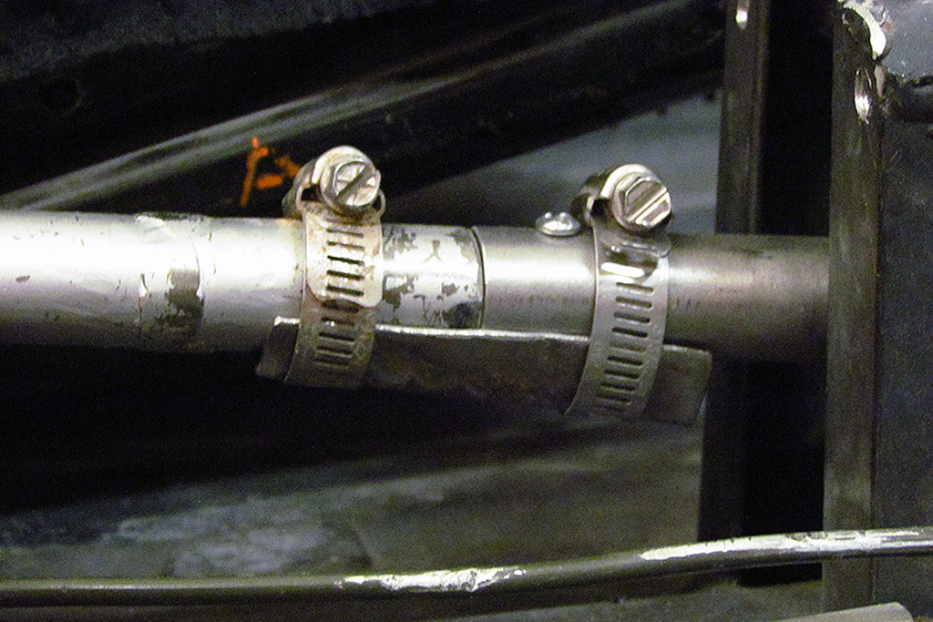
I also make a reinforcement for the shifter where it breaks apart.
That succeeds in keeping that rigid.
But...
With difficulty, I seem to find the gears, but when I attempt to change gears while the engine running and the wheels jacked up off the ground,
the wheels go around yet can be stopped with my hand, but does not seem to engage them.
I fear that, adjust of the shifter itself and the clutch lever, the shift rod may not be attached to the transaxle.
And the only way to access it is to pull the transaxle out.
It sounds like I may be starting over mechanically.
The engine does run, but everything else needs worked on.
FRIDAY JULY 17: Letting Go of the Baby...
So the chassis cannot move by itself and the box truck is coming at noon to take the body pattern away.
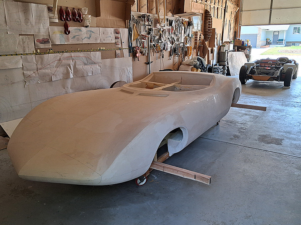
A neighbor and I found we could roll the chassis out of the way while inside the garage and roll the body to the garage door end.
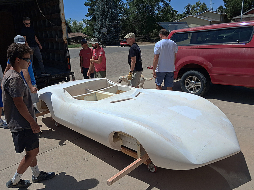
All the people and neighbors showed up to help move and load the body.
The box truck from Walter Composites showed up and the move began!
Out it rolls, slowly it is lifte up, and carefully it is rolled into the truck.
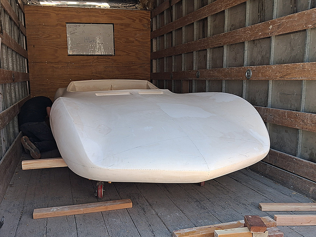
Boards are nailed down to keep it from rolling, the door is shut, and off it goes.
15 minutes flat.
I must admit, it WAS hard to entrust it into the hands of the fiberglasser, who is professional and knows what to do with the body, which I don't.
FRIDAY JULY 18: ... And Turning To The Baby Carrier
With the body gone, the garage gets cleaned up.
The first step is to sit down and list all that needs to be done on the chassis, and then priortize them.
The transaxle is not getting solved.
It looks like installing coilovers on the front wheels looks easy to do, so they get ordered.
They arrive and I begin the task.
By the end of the first day, I have run into problems.
They simply will not insert into the old shock+spring mounts.
I will have to start taking the wheel assembly apart.
First I detach the upper A-arm - no good.
Then I detach the anti-sway bar from the body - almost, but not enough to squeeze the coilover in.
Next I detach the brakeline from the disc brake - almost more, but still not enough.
What to do What to do??
Finally, I think I need to cut off the upper collar for the regular spring as the lower plate the spring rests on.
That involves a lot of cutting wheel and grinding down.
BUT IT WORKS
Check back for more progress!
The Build - 2026
January

1st ROW - Underpan & Louvres
(L) The rear underpan, plastered to shape and checked with a laser line contour.
(CL) Looking forward, with a center line and a cross line. There is exposed foam where heavy sanding happened.
(CR) The full-sized wheel well outlines being laid out for pinning the outline into the corrugated cardboard.
(R) It was as messy and ugly as this looks. Building up the louvre recesses. Note the sandwich bag full of plaster used to squirt it into the louvre, and the black putty knife for shaping.
2nd ROW - Wheel Well Contours
(L) The well patterns being glued up. Double thickness for rigidity and as a tracing surface for the pencil.
(CL) The rounded side supports will act as a shape guide for the chipboard sheet that the well opening will be cut out of.
(CR) Before the opening was cut out, this is a test fit to the body.
(R) The pattern with the chipboard removed. Shims were placed underneath to get the pattern to the correct height and horizontal placement.
February
1st ROW - Louvres & Wheel Wells
(L) The louvres at five feet. Looks pretty good!
(CL) Even closer, it looks very good. But check out those varying strake widths!
(CR) From this angle, the driver side looks really close. Some plastering is needed behind the front wheel.
(R) The bevel outline and the 1/2-inch guide used to make it.
2nd ROW - Wheel Well Bevels
(L) The front well with the bevel outline made 1/2-inch out from the wheel well opening.
(CL) The rear wheel well opening and the bevel outline.
(CR) The bevel after sanding. Note the gap between the bevel edge and the penciled outline. I sanded to it once, saw the bevel was too wide, and had to plaster it back on and start again.
(R) This is what it looke like when sanded to the penciled outline. Too wide!
3rd ROW - Interior Reinforcements
(L) Getting ready to place foam slabs inside the body cavities and cells.
(CL) The wheel well cavity in front of the rear wheel centerline. That lower piece sure look flimsy!
(CR) The wheel well cavity behind the rear wheel centerline. That's a lot of empty space to be supported by the exterior body surfaces.
(R) The front wheel well cavities. There is a LOT of empty space between it and the cabin space.
4th ROW
(L) ... for example.
(R) Two layers of foam, fitting tightly. It is a sturdy section... a strong core.
March
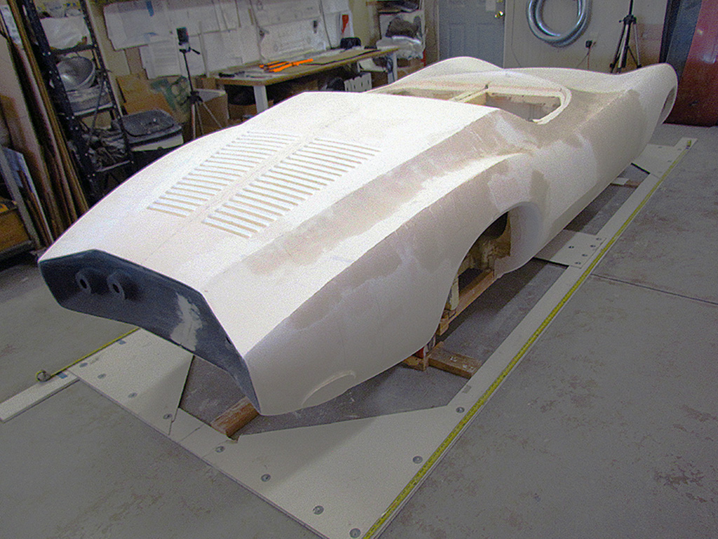
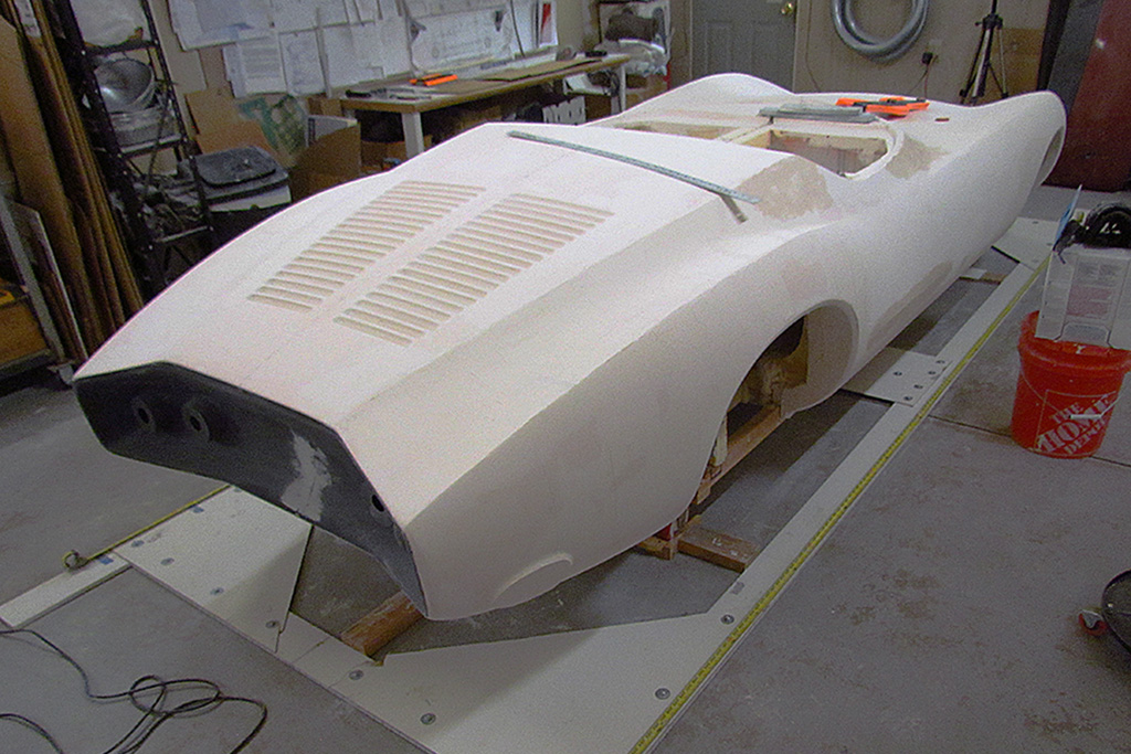
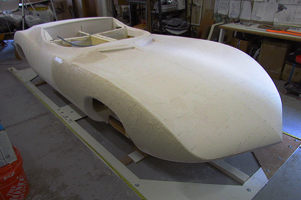
1st ROW - Working All Around The Body
(L) A foam strip is the base for the rear deck lip to be added.
(CL) Building up the door crease on the passenger side.
(CR) Building up the passenger side exhaust collar to match the driver side, and photos.
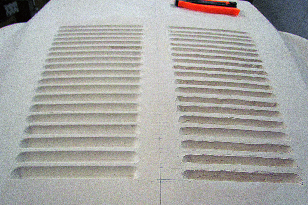
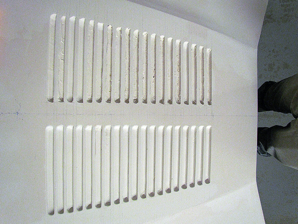
(R) Louvres look pretty good on the left, but much improvement needs to be made on the right. Mainly thickening the strake widths.
2nd ROW
(L) A close-up view. Note the pencil lines used to line up the strakes.
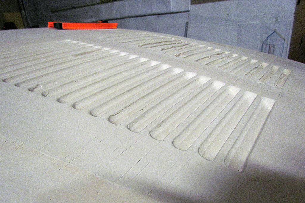
(CL) A look-down view.
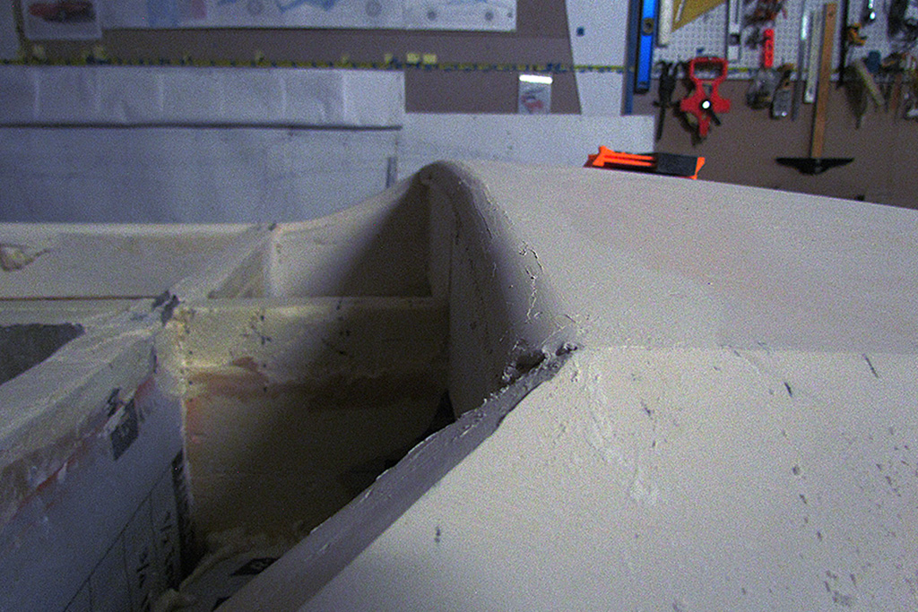
(CR) The rear deck lip after about three applications of plaster. Almost there.
(R) The louvres after some sanding-down and another application of plaster.
3rd ROW
(L) The setup for measuring the width from the centerline. Note the contour gauge. The 6-inch level has a pen taped on to do marking.
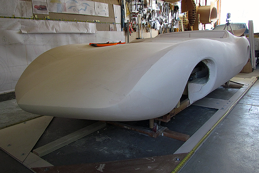
(CL) A state-of-progress view of the driver side.
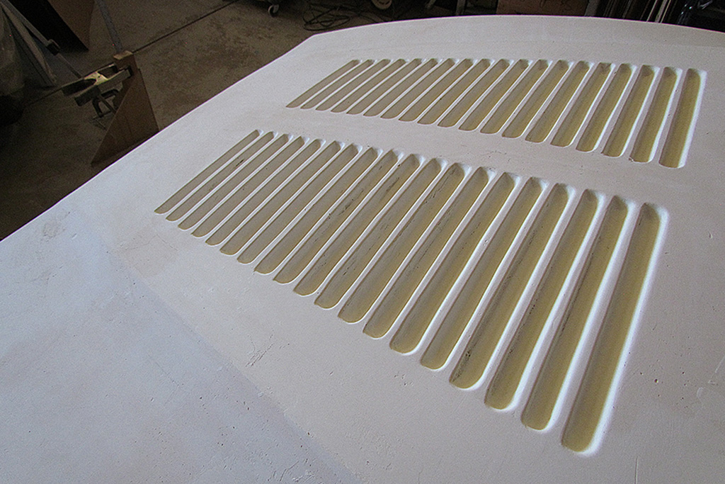
(CR) Passenger side louvres after sanding. There are still some problems where the sanding went thru to the underlying foam.
(R) In-progress view. Note the contour lines, mostly placed every 5-inches.
4th ROW
(L) The master set of contour lines on the driver side.
(CL) And the matching set on the passenger side. The door is a complex intersection of shapes from front and rear fenders and top surfaces. It actually pinches in about at the point where the side window is at its lowest point, before it curves upward to the rear deck. The door crease is 7/8-inch above the midline defined by where the upper and lower nose surfaces meet, which is the same as where the front and rear body clips meet the rocker panels.
(CR) Building up the rear fender top surface and the front of the door area.
(R) Yet another application as I get closer to symmetry.
5th ROW
(L) A lighter application to finish off the contour. Had to build-up the door crease after all my sanding.
(R) With the side dialed in, starting the front from door to nose. Lots to build up. The fender ridge needed to be moved out +/- 1/4-inch.
April
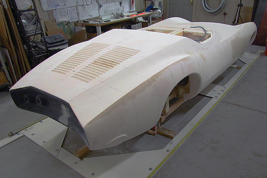
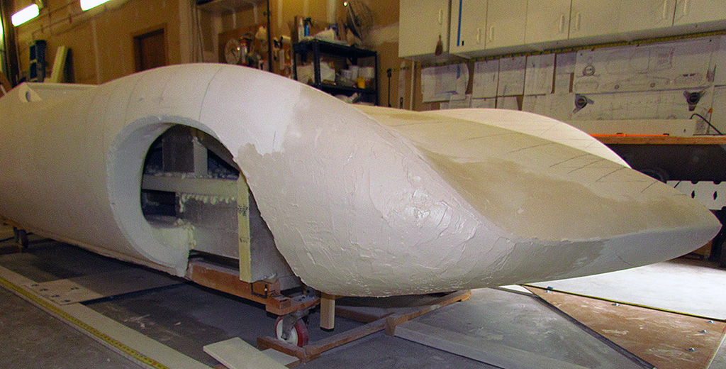
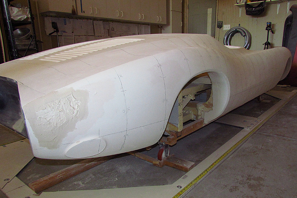
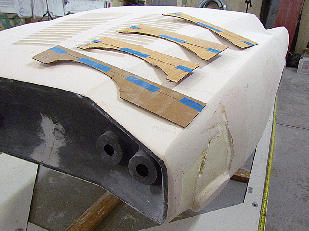
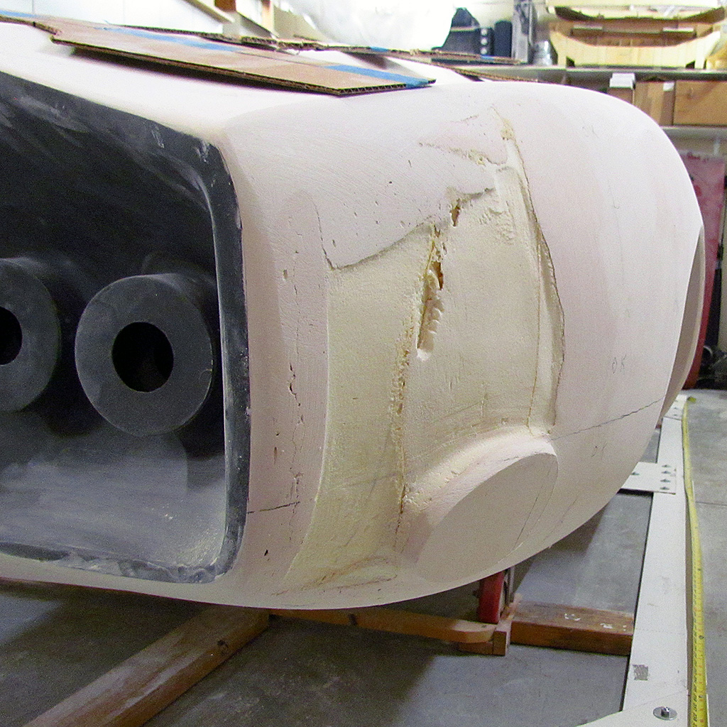
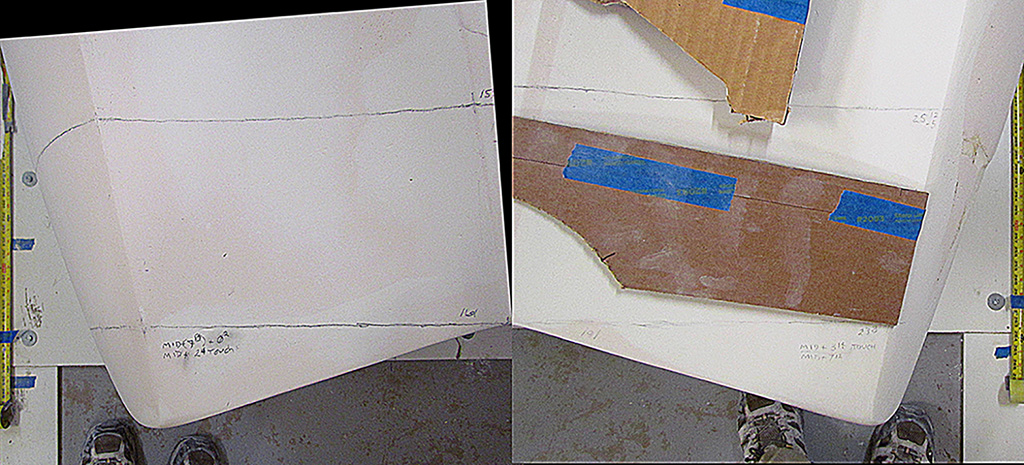
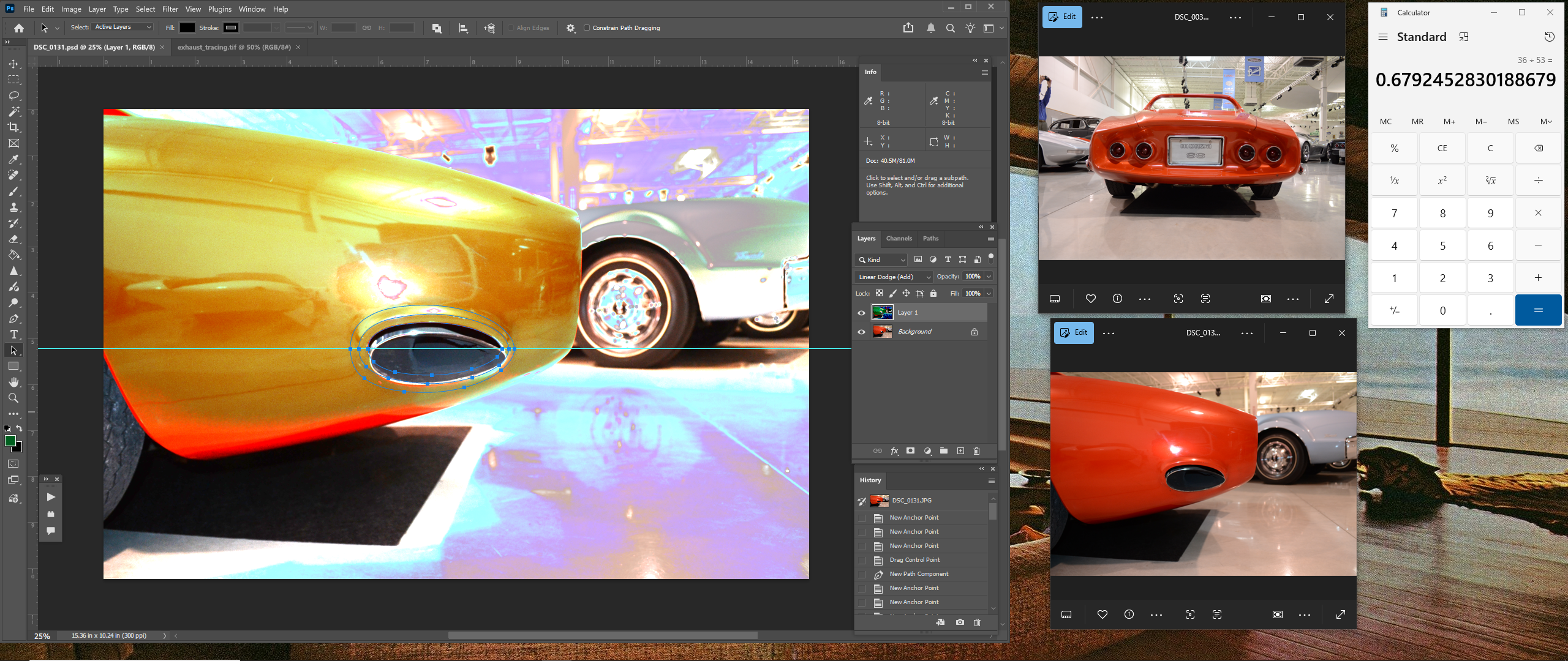
1st ROW - Contour Checks All Around
(L) Redefining the rear fender ridge, and making fuller the side behind the front wheel well. Also, more louvre touchup, but fewer louvres affected.
(CL) Still more side buildup.
(CR) How I do contours. The laser locates the contour using a tape measure on each side of the body.
(R) Here I have matched the passenger side to the contour guide taken off the driver side. Yay...keep moving on.
2nd ROW
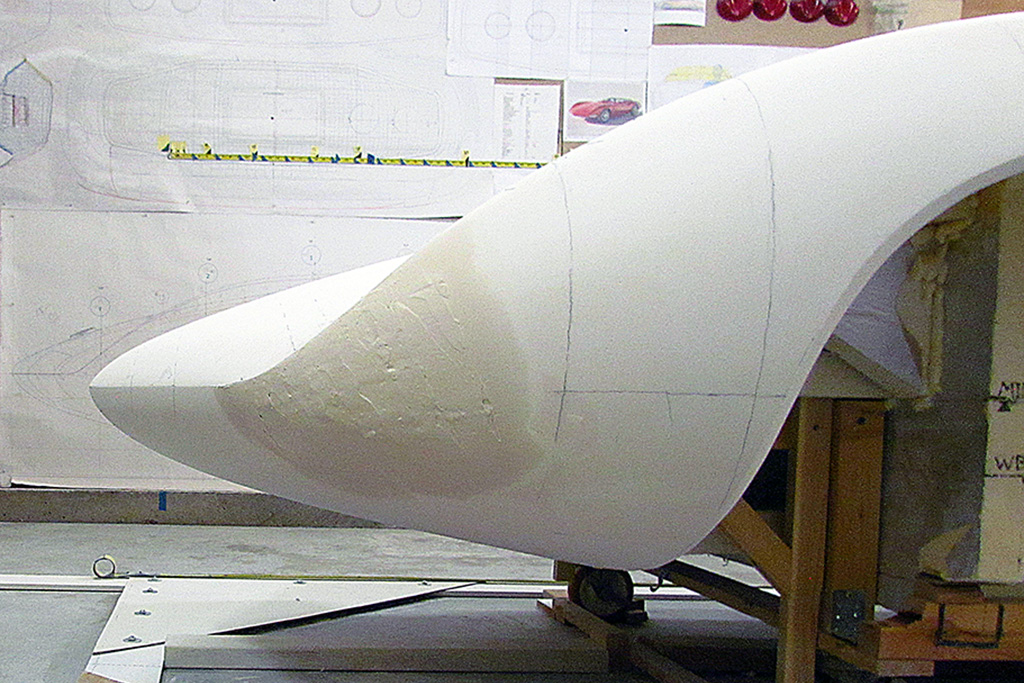
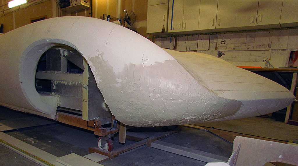
(L) The fender in front of the front wheel and the nose needed building up, and quite substantially where the fender turns down into the nose line. Even the passenger side nose profile looking down on it needed added width added, about 1/8+ inch.
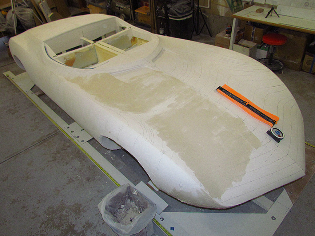
(CL) Building up the strakes where it was cracked or showing foam. (CR) While the fender dries, I use the laser horizontal line to plot the contours over the hood. It looked overall good with some divergence near the intakes in front of the window. The valley needed to be shifted out about 1/2-inch.
(R) I went back and studied the photos and determined that neither side was quite right. I decided even the driver side needed to be fuller - more rounded.
3rd ROW - Fixing the Passenger-Side Nose
(L) Another big buildup on the passenger side.
(C) A nice side view of the driver side build-up area.
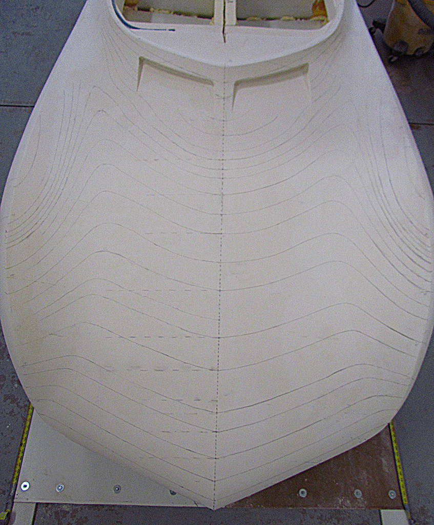
(R) Tracing horizontal left-to-right contours and observing their intersection with the vertical left-to-right contour allows me to check for left/right symmetry by measuring the intersections relative to the front-rear centerline. Is that clear???
4th ROW
(L) Building up the right front fender. It needs to be fuller, i.e., more rounded.
(CL) Same goes for the top of the hood, according to those contour intersections.
(CR) Sand it down and do another application to the passenger fender. Note that the coverage is increasing. It extends farther, but is applied more shallowly because it is approaching symmetry.
(R) The passenger rear fender contour doesn't quite match the other side. And it keeps breaking thru the plaster to foam base.
5th ROW - Fixing the Right Rear Fender
(L) I finally decide I need to sand it down and start again building it up. This time I make a set of contours for about every 5 inches along the fender.
(CL) A close-up of where I begin the rebuild.
(CR) A left/right comparison of the rear fender profile.
(R)
May
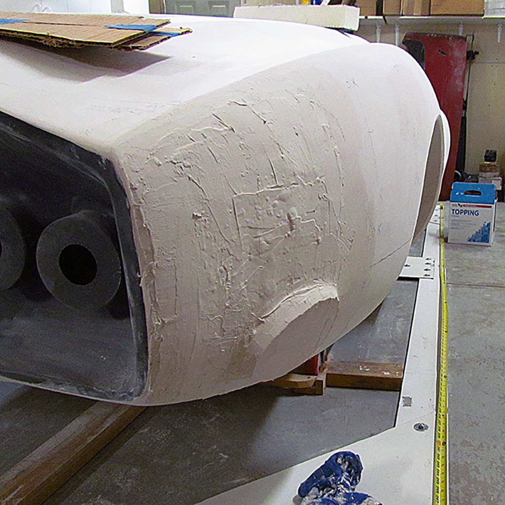
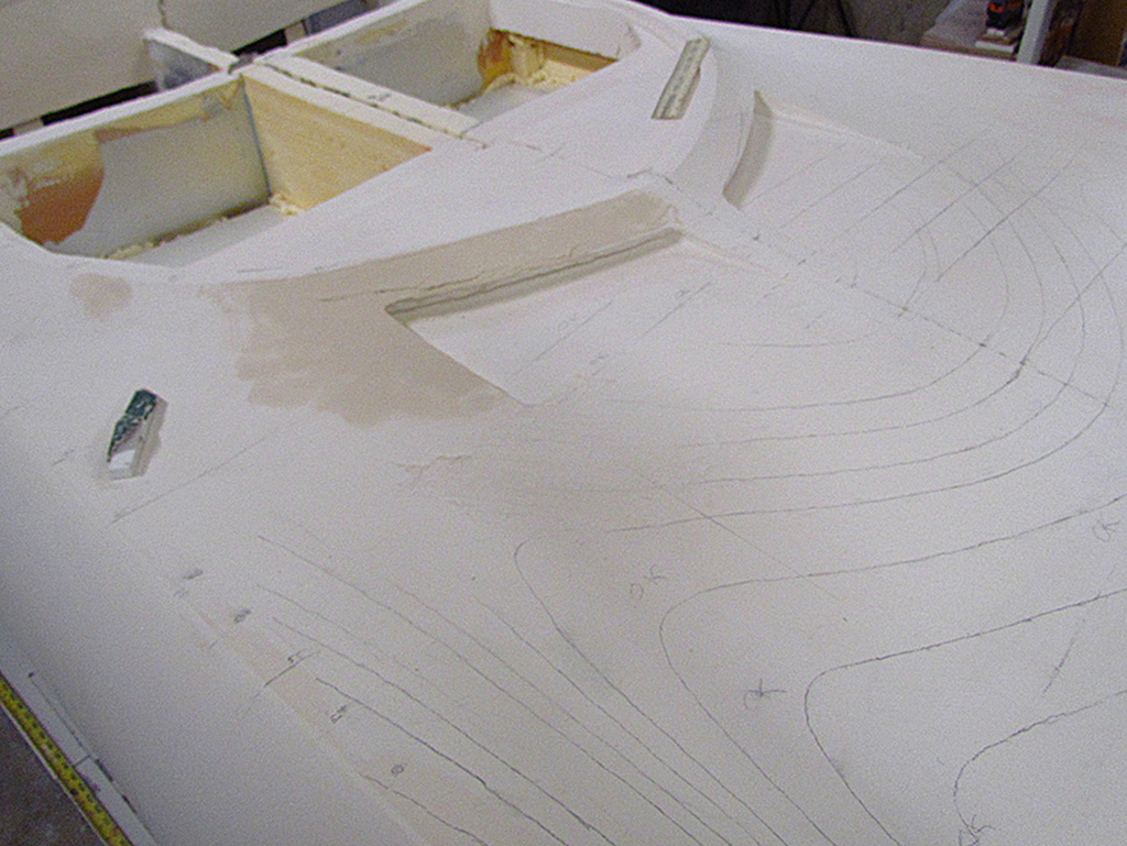
1st ROW - Touch-Up Plastering
(L) More plaster for the rear fender
(CL) Building up a flat spot by the front air intakes.
(CR) Refining the door side crease.
(R) Smoothing out the front underpan. Note more cross-contour intersections with marks noting where the intersections ought to fall.
2ndt ROW
(L) Matching a contour of the left rear fender, using it as my master.
(CL) Applying it to the right rear fender to see if I need to add more plaster.
(CR) I do, and I work it to both fill in low areas and to work the surface smooth.
(R) And then last of all, building up the bezel around the exhaust port.
3rd ROW - Redefining the Front Intakes
(L) I discovered I had the air intakes positioned too far forward. The windscreen and side windows have a painted stripe across their bottom edge that hides the attachment area. They all are screwed onto the rim around the body. Here are the tools I used to reshape it.
(CL) This REALLY shows how off the left/right symetry can get.
(CR) Here I am using the laser contour as a guide to sand and plaster the shape.
(R) And finally, I cut the excess lip off and redo the corner rounds.
4th ROW
(L) The view after repositioning and reshaping the intake leading edge.
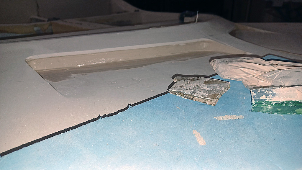
(CL) Applying plaster to the recessed vertical surface that represents the intake grill. Note the sandwich bag full of plaster on the right. I squirted it out from this, like a cake decorator. The cardboard piece is used to make it a uniform depth
(CR) Repairing the perimeter surface of the cabin outline
(R) And a confirming contour symmetry check.
June

1st ROW
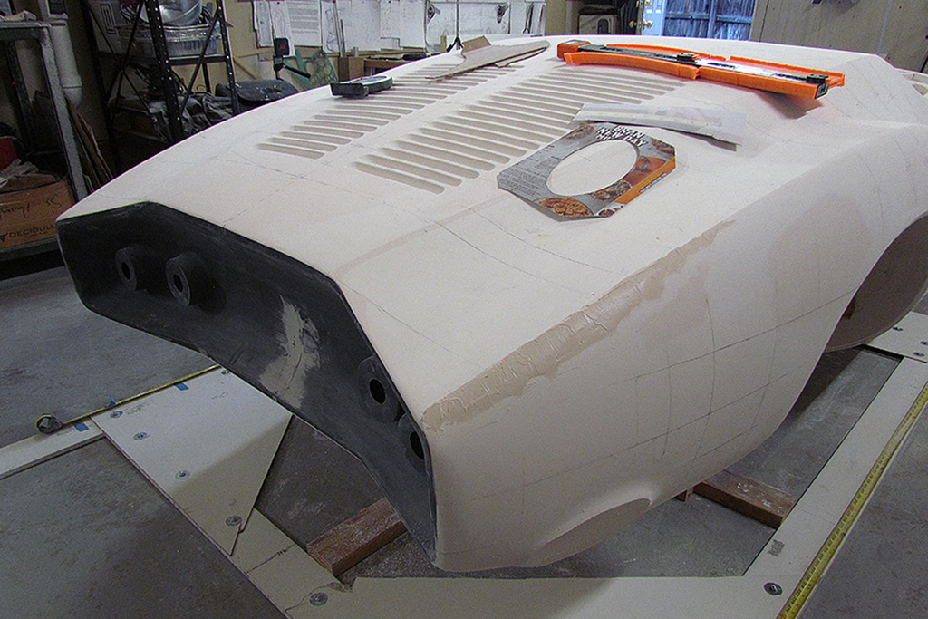
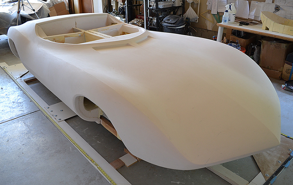
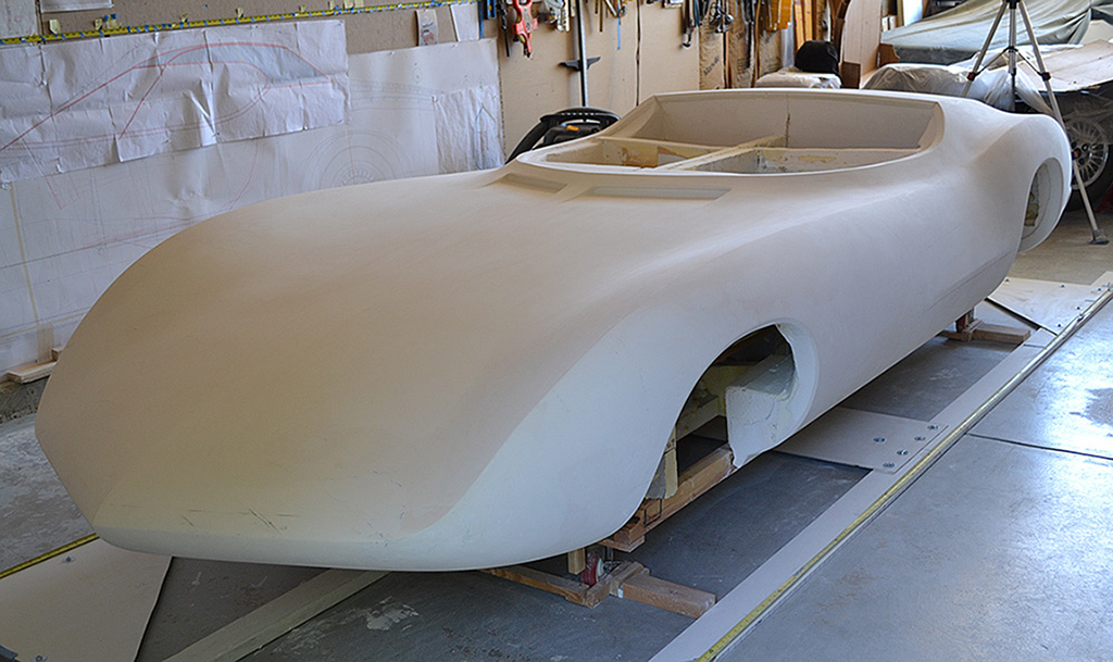
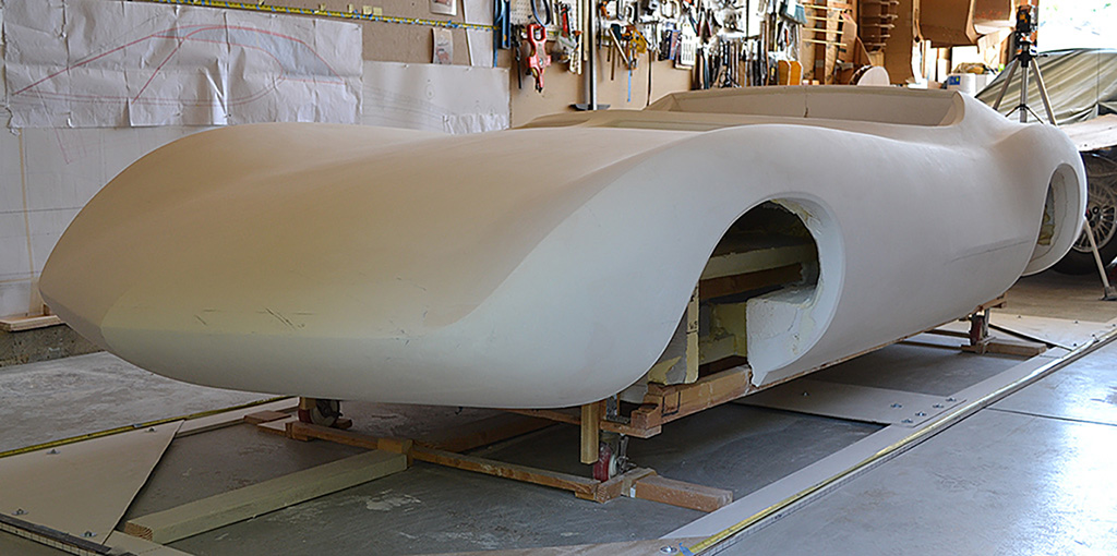
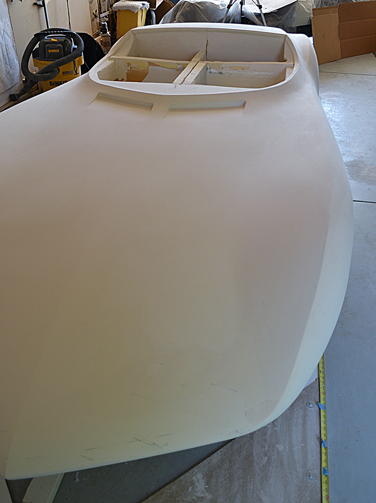
(L) Tools and templates used to shape the exhaust port platform. Note the laser symmetry check.
(CL) Shape check: left & right rear fenders
(CR) Touching up the fender ridge... again... and again.
(R) Redefining the right front wheel well and bezel.
2nd ROW
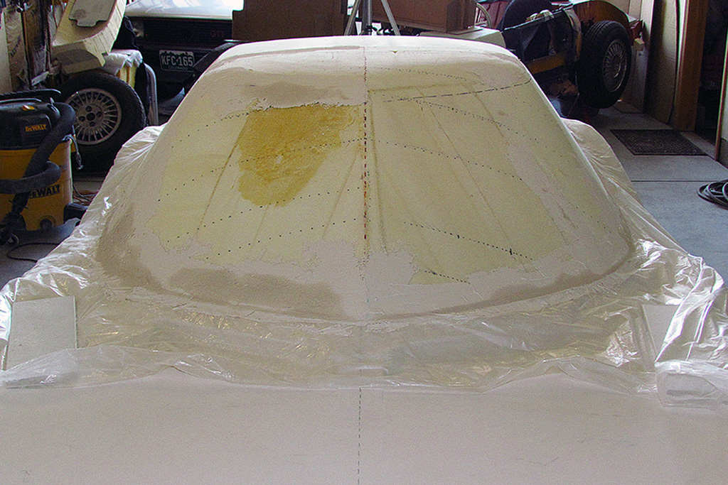
(L) The passenger side of the top is roughed out to match the driver side. Plastering has been applied to the cabin outline to make the top fit the shape. The dotted contour lines are looking close to symmetrical.
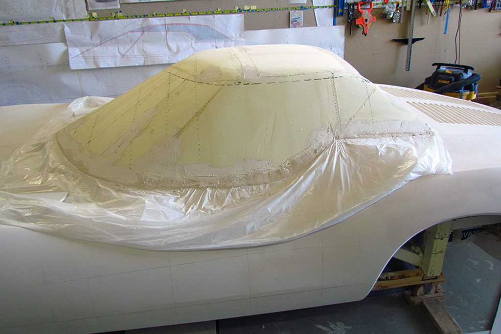
(CL) Side view. This is the master side. Note that the rear window (not shown) will be nearly vertical and approx. across where the rear-most vertical dotted line is on the B-pillar.
(R) Nearly complete. This lighting begins to show the shapes and ridges.
3rd ROW - Walk-Around
(L) Plaster is so hard to judge the smoothness of the shape. It looks like there is a slight undulation just behind the cabin area as it rises to the rear deck.
(CL) I see a slight unevenness in the front fender ridge from the wheel well back. The horizontal door ridge line looks good.
(CR) The hood and front intakes look good from this angle, as well as the cabin outline.
(R) Notice the slightly tan coloration. One batch of topping came that way, making it harder to judge smoothness because it looks like a shadow instead.
July
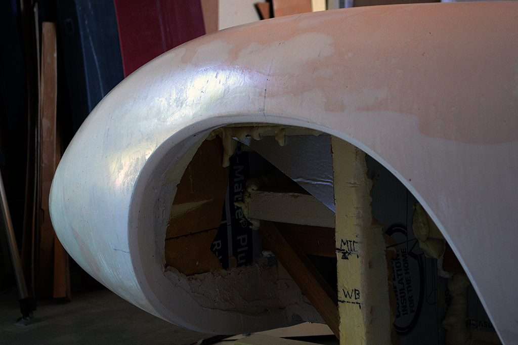
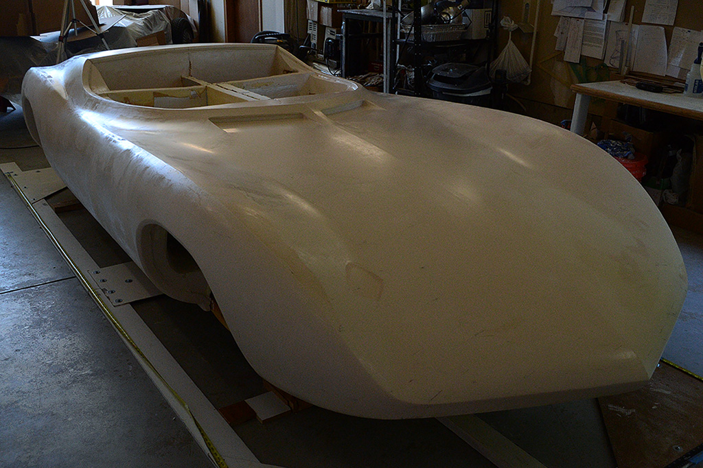
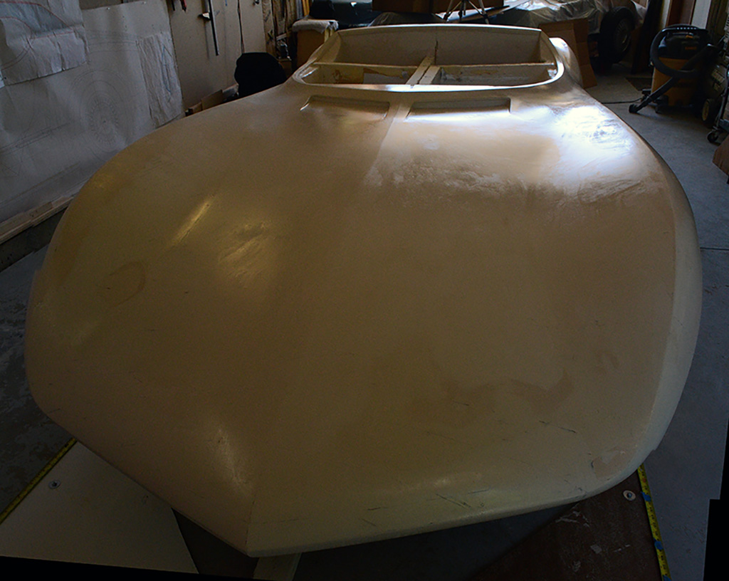
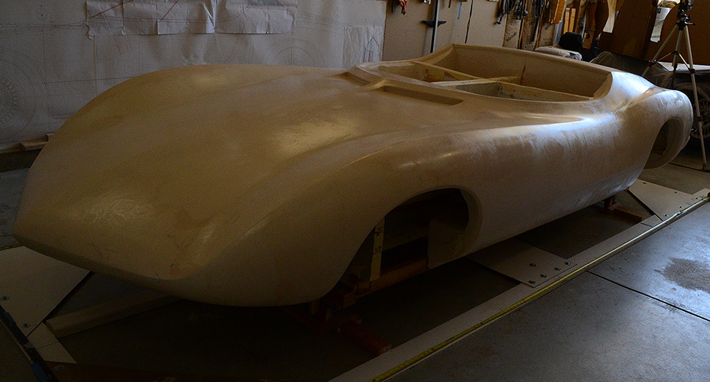
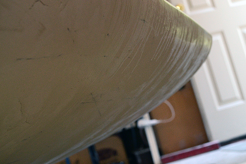
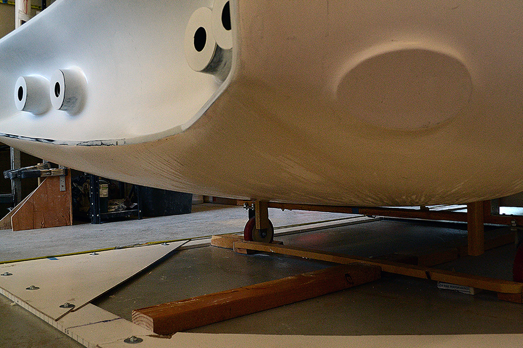
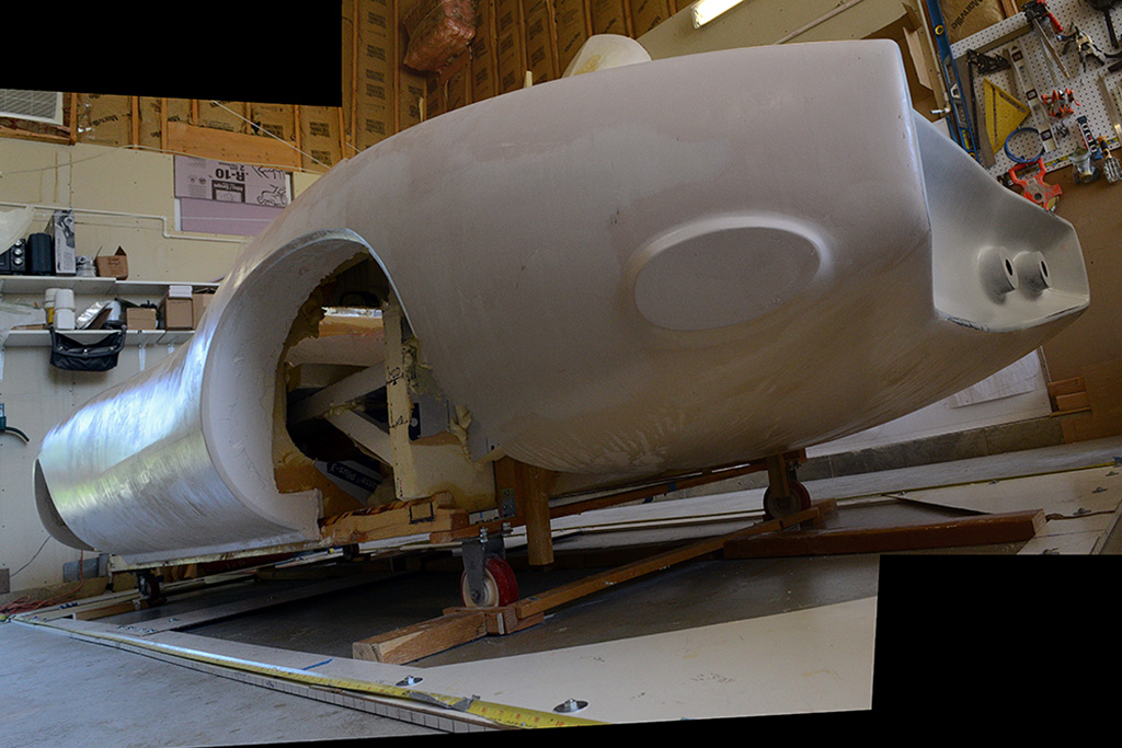
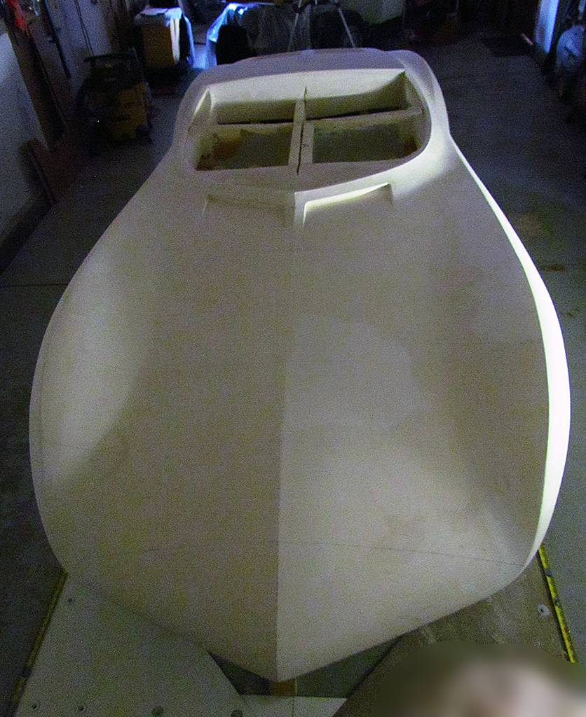
1st ROW - Surface Hardening
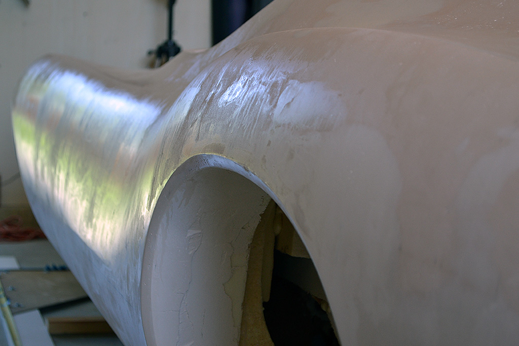
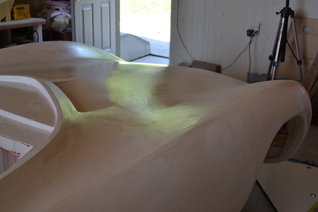
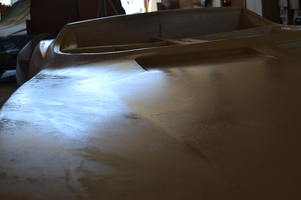
(L) The surface contours look good, but the hardener did not apply evenly. I part, I think the plaster absorbed it unevenly.
(CL) When dry, the surface was hard and no more plaster powder would wipe off. But the hardener puddled unevenly, as seen on the flat-ish surface of the front clip.
(CR) The backlighting reveals the ugliness.
(R) front fender ahead of the wheel well.
2nd ROW
(L) You realize what this means, don't you, Rich?
Yes... a lot of sanding smooth and maybe reskimming.
That's right. Plan on an extra week.
(CL) Oh, if only I had a spraygun to apply it!
(CR) The more I look at it, the more depressed I get.
(R) Start planning how to attack it.
3rd ROW
(L) If I sand it too vigorously, it will break thru to the plaster and require building up.
(CL) I am pleased how well the intakes came out.
(CR) A crisp door ridge line and smooth side contours
(R) This view of the nose shows the problem with the very viscous spray. It ran.
4th ROW
(L) The rear underpan also shows
(CL) Another view of the rear quarter and underpan.
(R) A single-source side light does a good job of showing the contours and ridge lines.
5th ROW - Final Walk-Around
(L) I love that center ridge as it fades up the front clip and then pops out again before the cabin. It actually needed some toning down right where the windscreen begins.
(CL) Note the sanding patches on the kamm cove. Since it will be primered at the fiberglasser, there was no need for me to apply cover-up paint.
(CR) A high view, front.
(R) A high view, rear.
6th ROW - Installing the New Shifter
(L) Bolt-down bracket pattern and part for the new shifter box for a Type 1 (Beetle transaxle) shifter
(CL) Front bracket in place. It attaches to the two seat front supports.
(CR) Shifter placement test. Note also the shift rod. A new reinforcement piece is added to make it rigid at the break.
(R) Close-up of the new reinforcement V-shaped piece. Usage reveals an additional piece on top will be needed to eliminate all wiggle here.
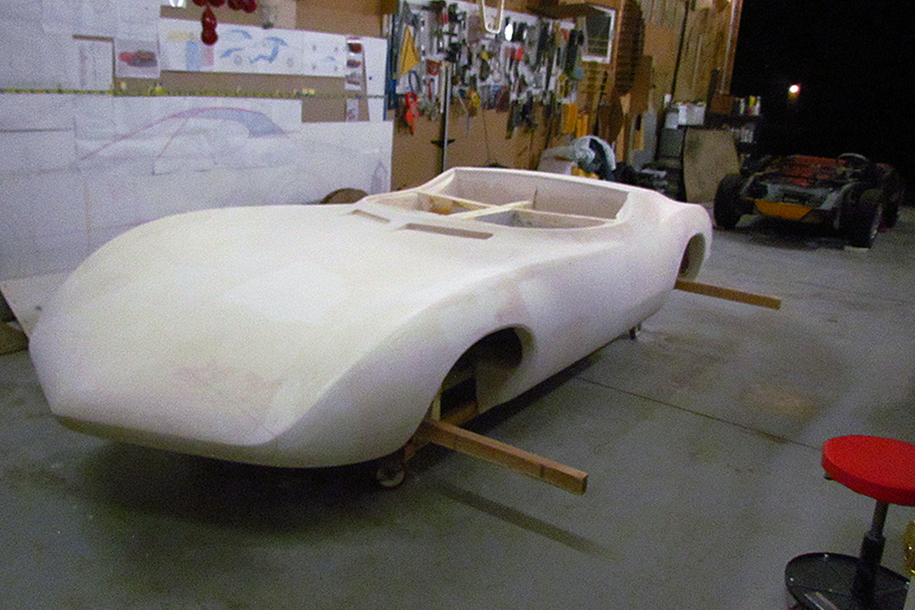
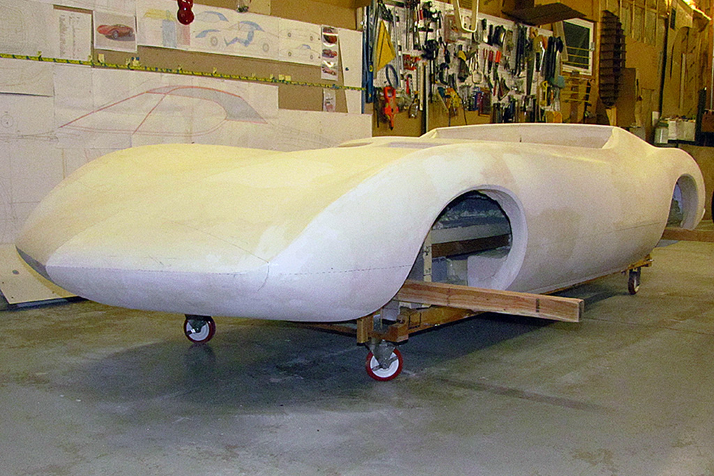
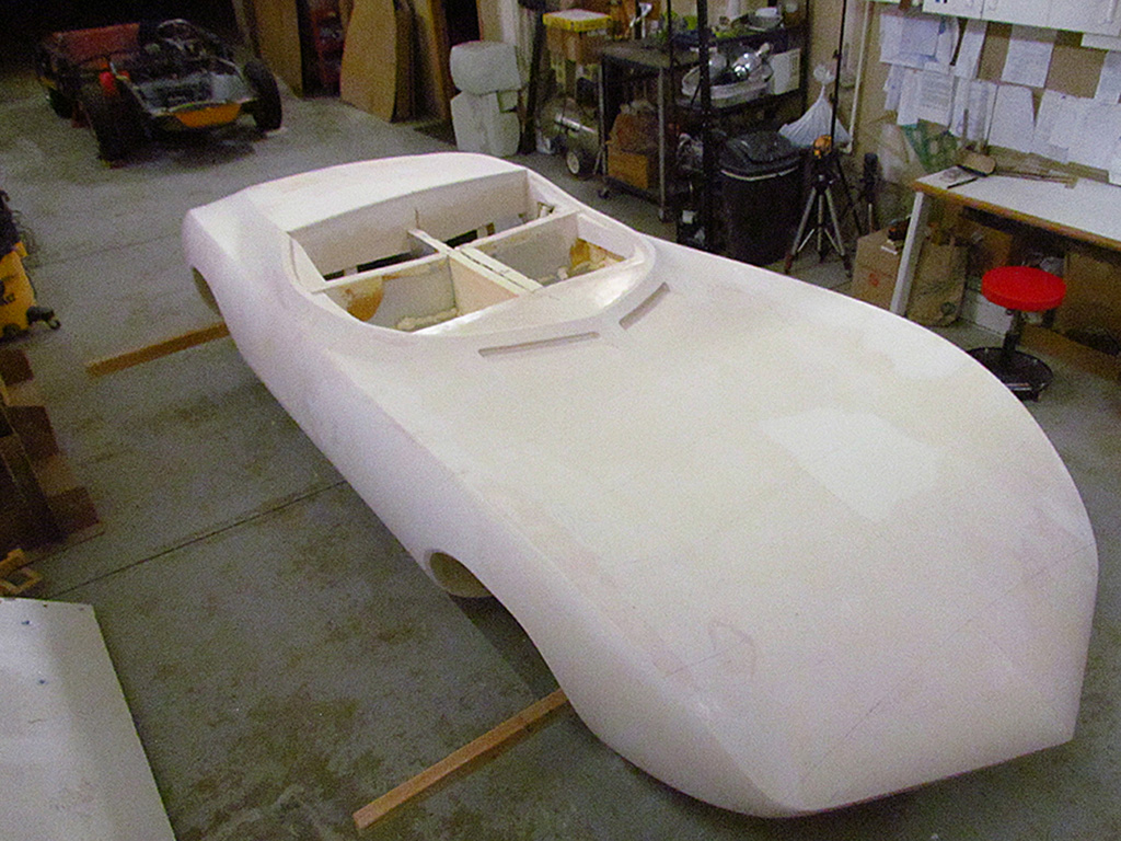
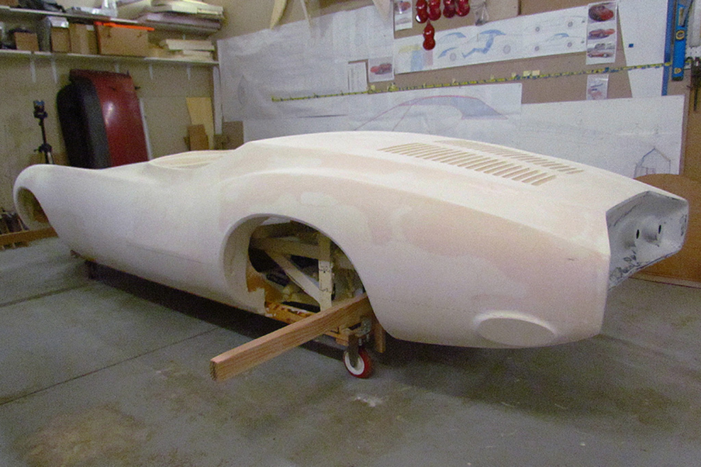
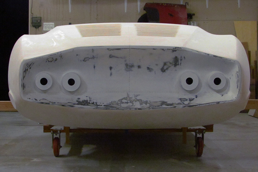
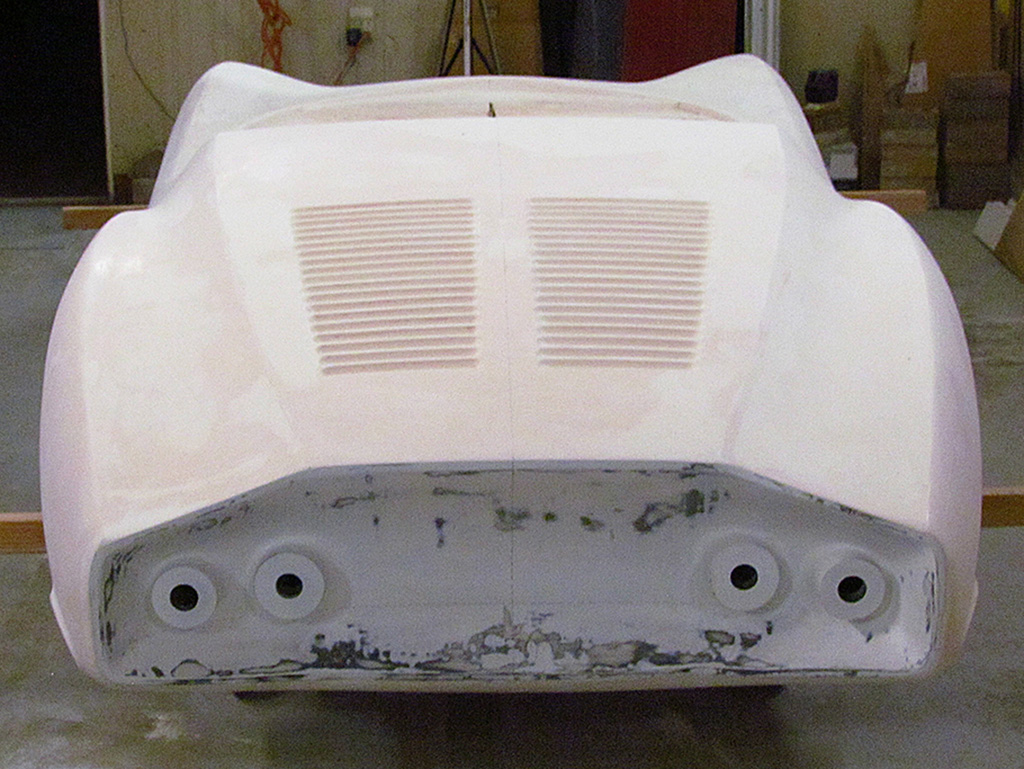
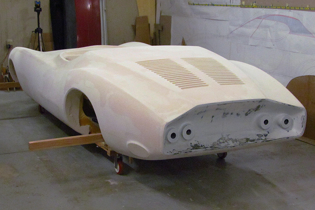
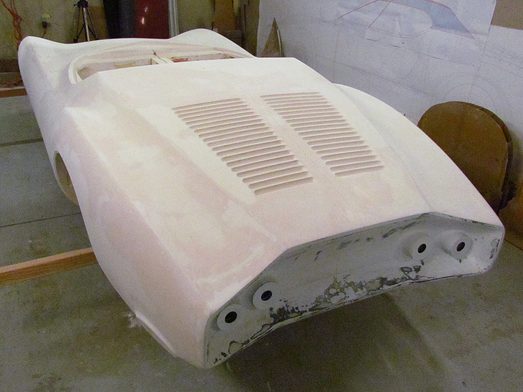
1st ROW - FEBRUARY 16, Prepped For Moving
(L) The 2x3x96 lifting bars are installed.
(CL) My 81-year-old neighbor and I test-lifted the rear end (208 lbs) to our waist with no problem. It did not feel heavy at all.
(CR) I had cut openings in the centerline piece of foam and the bars slipped right in under the two length-wise rails.
(R) The whole thing moves easily, and carefully, around the garage in the dolly. I can do so by myself.
2nd ROW
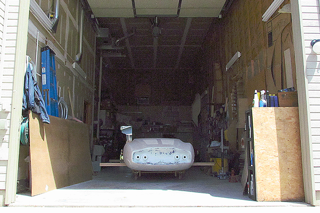
(L) End view. Ready to go.
(CL)
(CR)
(R) It is all ready for the morning
3rd ROW - FEBRUARY 17, Moving Day
(L) I was unable to get the shifter to engage the wheels. So I put the chassi on rolling plates and my neighbor and I roll it to the back and roll the body to the garage door.
(CL) There it sits waiting for the box-truck and helpers to lift it.
(CR) At 12:10 the event begins.
(R) At 12_25 it is in are 2x4s nailed down to keep it from rolling and it is ready to go to Denver.