Warp Drive . . . so, how DID they make those nacelles work in the original TV show???
. . . derive accurate orthographic side view
On a low-res TV set of the 1960s, the engine effect was fabulous!
I used to photograph the TV screen as the only way to capture details of the sets and models.
But we could not figure out how it was done.
Fast forward forty years. VCRs have come and petrified - they could not answer it.
PCs finally became powerful and affordable and the software available to do screen captures, but the resolution was iffy.
Finally the DVDs came along and now we can see it in all its simplicity.
Now I know what to look for. Now I know what I am seeing.
It has lost some of its wonder, but the effect holds up well.
Datin's solution was ingenious. I suspect it worked out better than he expected.
I still wonder if part of the effect was due to some time lapse.
Did during some of those dolly shots, did they go CLICK MOVE CLICK MOVE CLICK MOVE etc.?
That may be depending on the amount of light available and the film speed used.
Still, there are shots that look to be done in real time.
Any way, the next step is to build it full scale with the same lights and motors.
Then the next step is to program it into a chip and LEDs and put it in a model.
Did you hear that CultTVMan is taking advance orders for Polar Lights' upcoming 1/350 TOS Enterprise?!?!
I gotta be ready for that one.
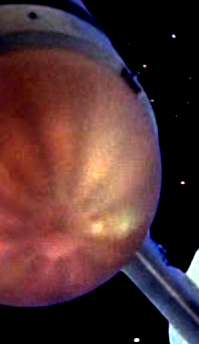
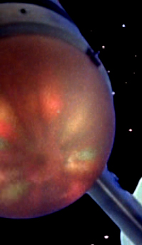
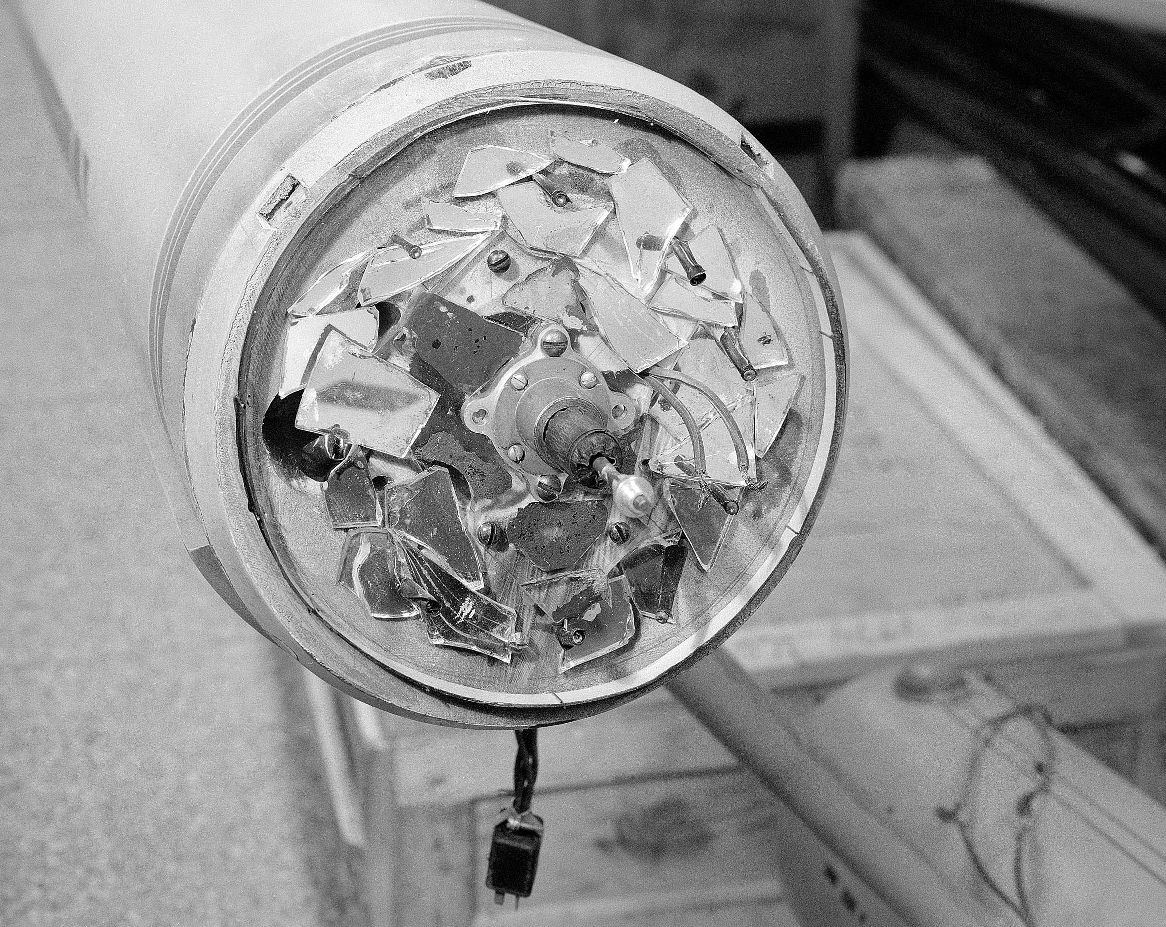
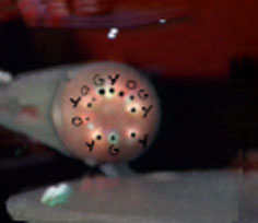
Take a rotating fan...
Add blinking mini-lights...
Use nine per engine...
Add some mirrors...
And you get this!
...and this!
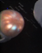
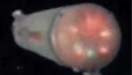
Port side close-up of the bussards without the domes
Tracing of Stbd nacelle... and overlaid on photo
Attempt to assign colors to lights
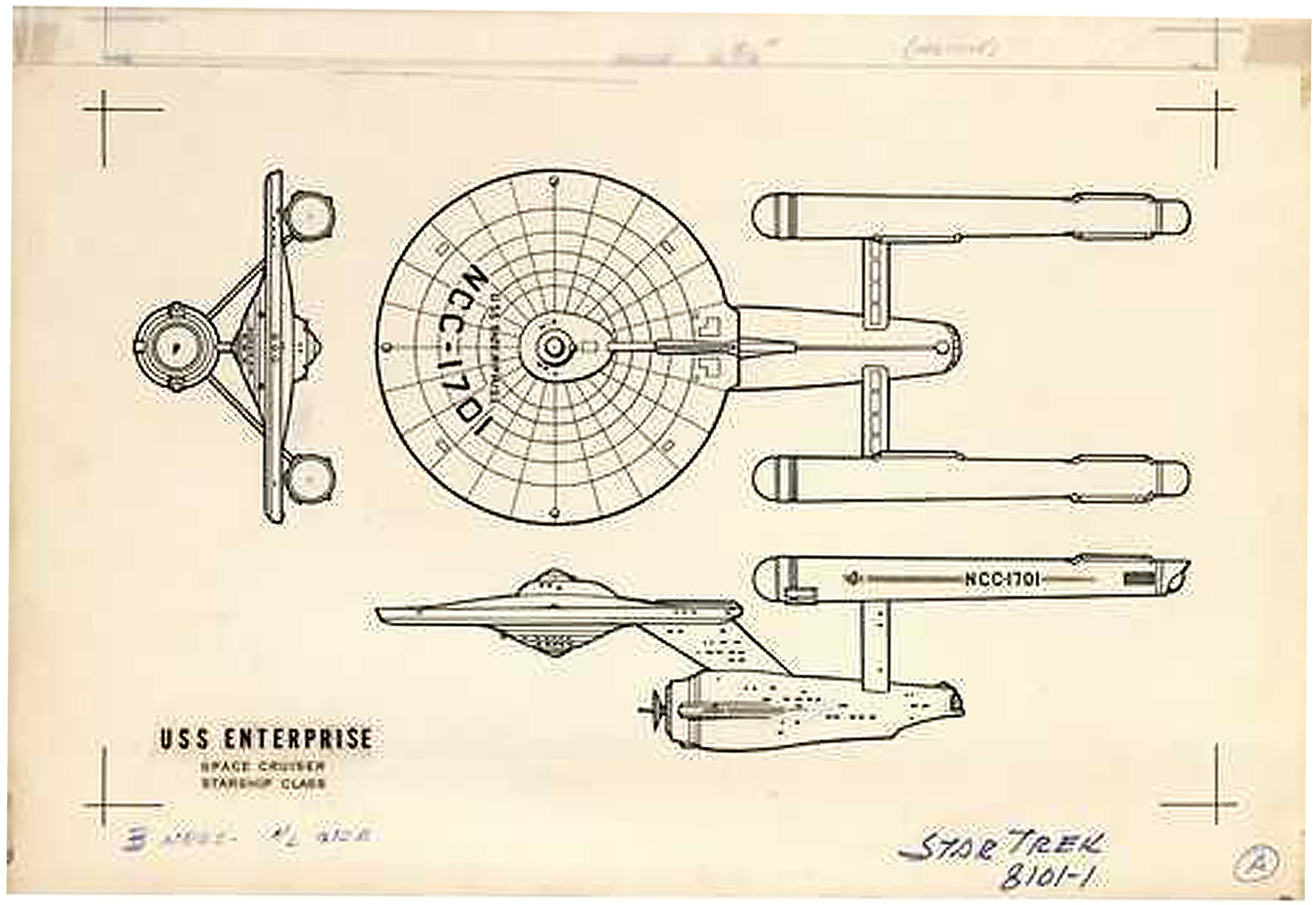
Ship Lines
. . . derive accurate orthographic side view
At issue is working with an image with enough resolution.
My first attempt combined two screen captures of a simple pan shot.
In this case, the model remained in place and the image was simply panned across the screen - PERFECT for my needs!
I just stitched the two caps together, but the resolution is not great enough to deal with perspective distortion.
The second attempt worked with a close up of a pan in which the model moved by and the camera was static.
I worked with nearly a dozen images, each one captured just slightly later than the previous.
I then chose the center point to the viewer of each one and attempted to match it with the one before and the one after, blending the seam.
This was done in Photoshop.
Note that no perspective correction was attempted - I was trying to obviate the need for that because at that time I had no tool to make the correction.
In the first example, I tried to scale the engines as if they were lying along the center line.
The second example shows things just as they appeared without jiggering the engines.
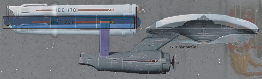
The 4th image takes the 2nd image and layers an illustrated elevation view of Sinclair's drawing, and then adds a tracing of multiple images, which I had scaled to each other without corrections.
Those tracings were a crude attempt to find an accurate outline by simple averaging. I don't recommend that technique.
As can be seen, things corroborate pretty well - engines excepted.
And finally, I include a comparison of details, made public on TrekBBS, as worked out by David Shaw.
. . . derive accurate resource plans
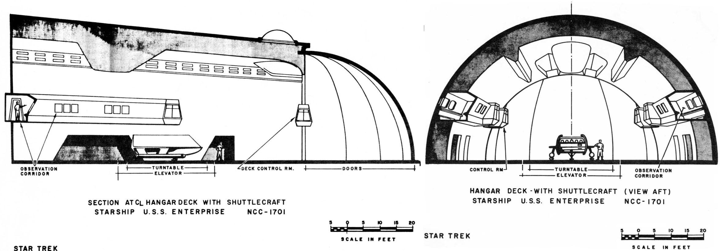
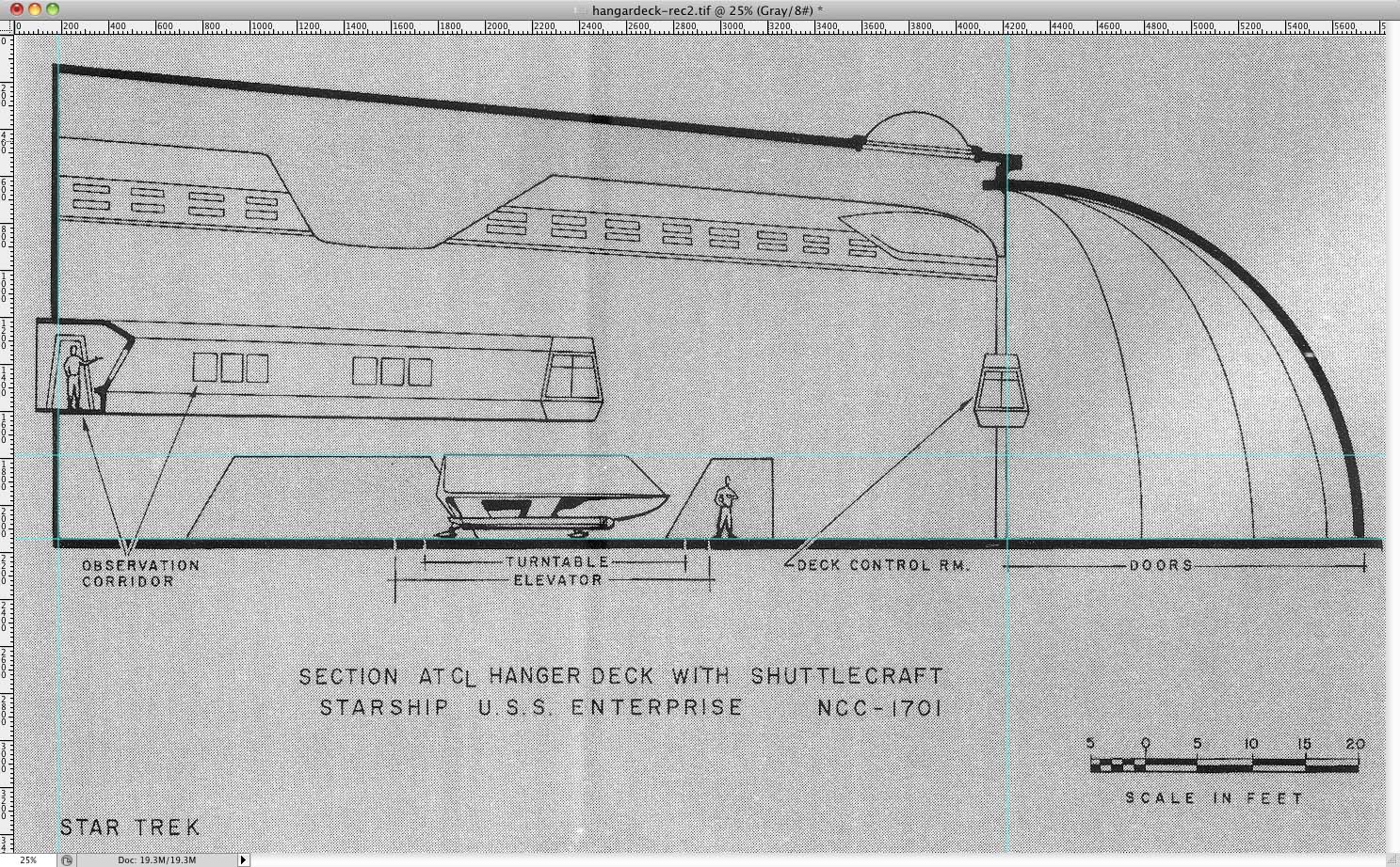
The second set revisits the published plans of the starship in 3-view and cross-section, and the hangar sectional drawing.
The sources are images posted on the web of the scanned original drawings (found here),
and supposedly original but more detailed versions published in "Star Trek Sketchbook".
I Huginized them first to removed photographic distortion and then checked them for vertical and horizontal scaling.
The web images included the crop marks, so those were used for control points in Hugin.
And the results were just about right on - without need for disportional scaling!
Scaling was checked first by making the primary hull circular - if it needed the correction.
Then the side view was scaled to the top view.
The side view needed a pinch of enlargement to make the saucer diameter match.
The Sketchbook drawings required the use of horizontals and verticals from the drawings themselves since there were no crop marks.
Although the line work is finer and the images are larger, discrepancies were more pronounced.
I could not quite get the top and side views to match.
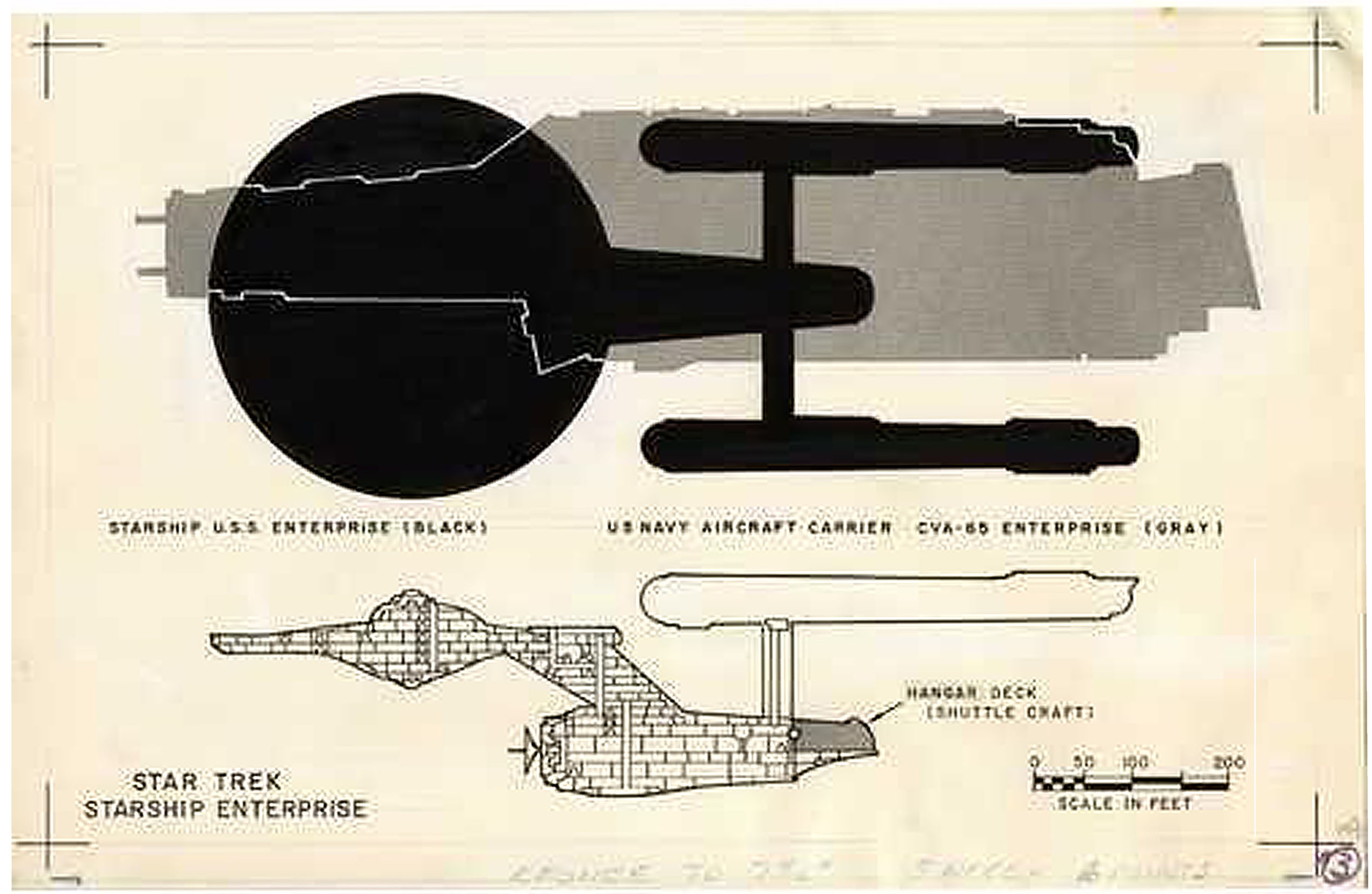
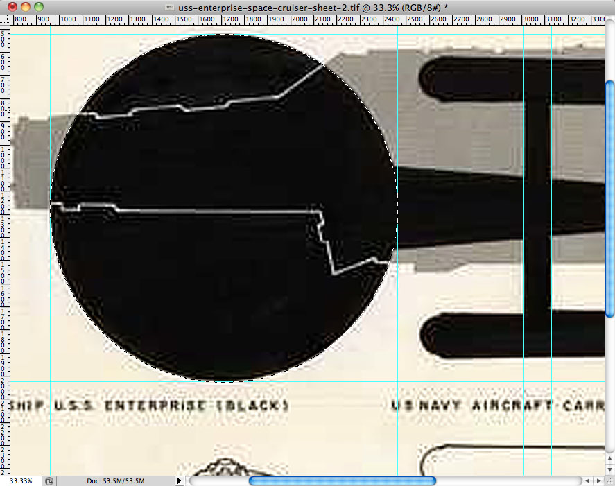
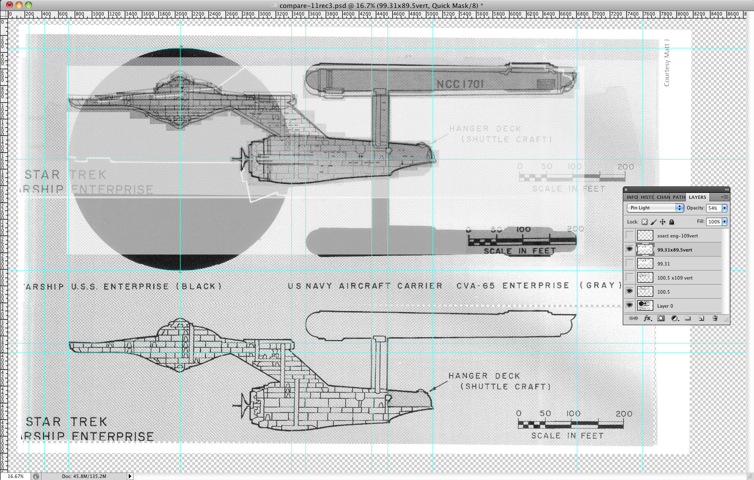
A NOTE about the top view comparison of the carrier to the starship...
In 1966, the carrier USS Enterprise CVN-65 had a length of 1101 feet, which I believe includes the catapult extensions on the bow.
That length remained constant until its 1991 refit, which lengthened it to 1123 feet.
Obviously its length when the drawing was produced would be 1101 feet.
Now, when measuring mechanical drawings done in the manual drafting days, one always measures from the MIDDLE of a line to the MIDDLE of another line -
no matter the thickness of the line.
That is because the center of the line is always the center of the drawing nib.
So that tells us where to measure lines on mechanical art work.
Because the carrier is a solid, one can fudge a few pixels to get its dimension.
Doing so results in a measured length of the starship of 916 feet.
But those catapult extensions look too long.
I found on the web HERE a dimensioned drawing of the flight deck as it was designed.
Using this as reference, I came up with a NCC-101 length of 934 ft. and saucer diameter of 408.9 ft.
MUCH closer! I will keep working on it to see how close I can come.
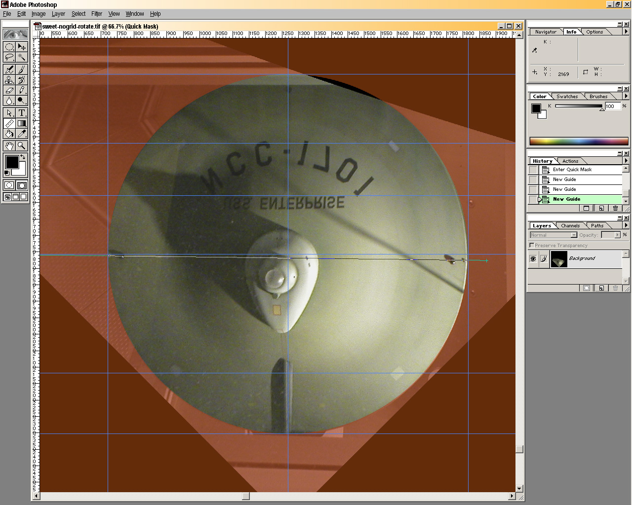
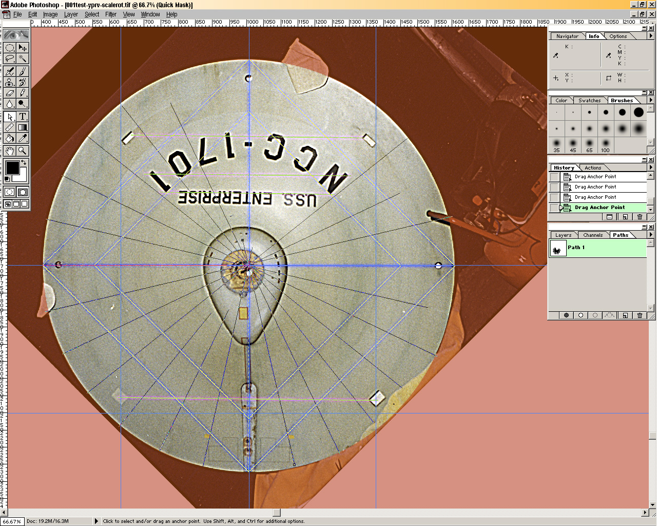
. . . derive accurate orthographic top view of primary hull
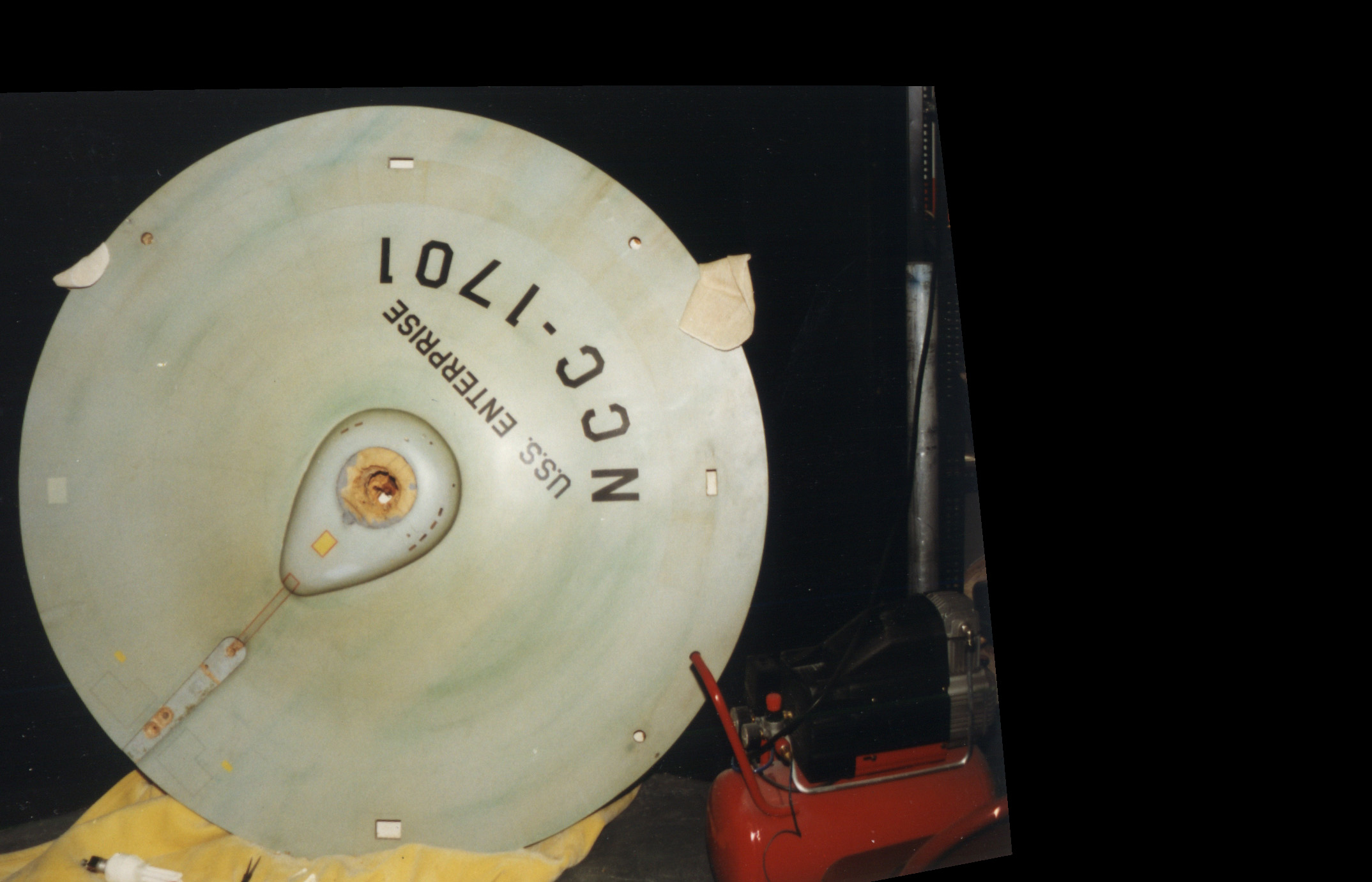
I managed to photograph the primary hull top surface reflecting off the ceiling mirror in the Air&Space Musuem gift shop.
It is the only original surface of the model from the original TV run.
But the model is slightly tilted, so how does one correct for perspective distortion?!
Why, use Hugin, of course!!
I shot a grid to calibrate my camera for barrel distortion correction in Hugin, but my results were unsatisfactory.
They are close as it turns out, but closer examination reveals disturbing evidence that it is not quite there.
Note how the rear two rectangular lights do not align horizontally.
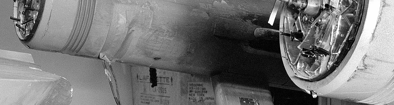
At THIS LINK are photos of the model being restored in 1990 from the collection of Mark Dickenson.
This one shows nearly the entire to top surface and in much better detail than what is possible at NASM!
I ignored barrel correction, having no way to calibrate it.
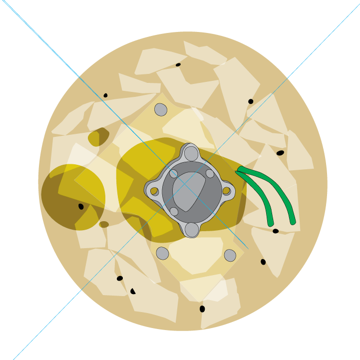
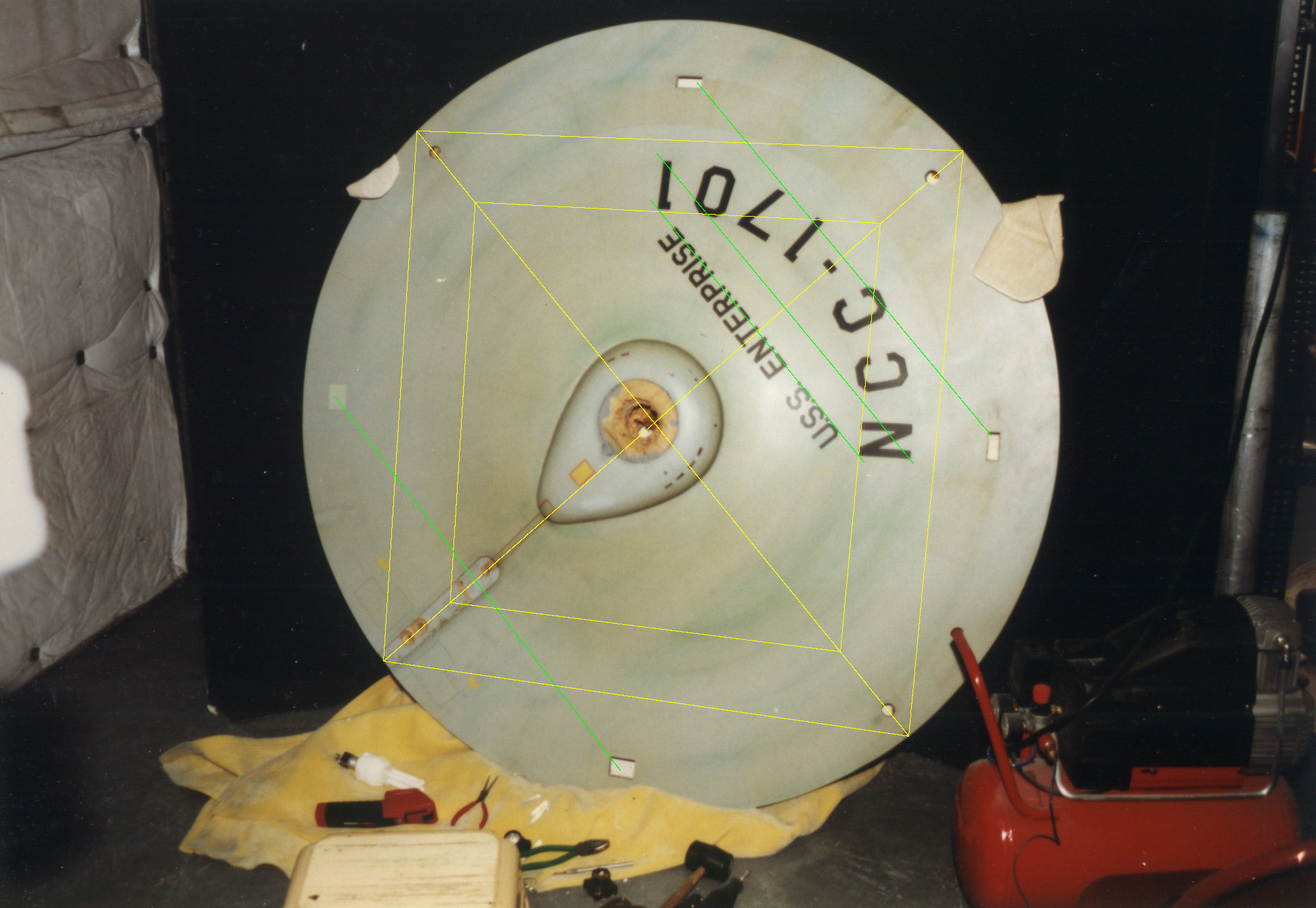
I assumed that the port and starbord running lights were on the horizontal center line, and drew my control lines in yellow accordingly.
I added the green lines for the lettering and rectangular lights for reference.
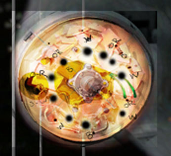
I Huginized and examined it in Photoshop.
I placed guides at the tangents to the saucer perimeter and drew an oval selection to see how well the saucer outline matched a perfect oval.
Turning on masking, I look if there are similar gaps on opposites sides of the saucer.
If so, that means that I am not yet parallel to the plane I am correcting.
The gaps are an interesting issue.
Apparently Gary Kerr found the saucer has an irregular diameter (not unexpectedly), but by how much?!?!
He gave an average diameter dimension of 59-3/4", I think.
At the size I am working, that is about 5 pixels.
If anyone has contact with Gary, could you ask him what the minimum and maximum diameters were that he found?
Assuming again that the saucer should be circular, not ovoid, I scaled the X and Y axes to be equal, and then rotated the center line axis to the vertical, about 45.3 degrees.
Things were still close to circular, but now I could examine different relations ships in my corrected plane.
That plane extends from the rim to just past the "rust" discolored band almost up to but not including the NCC-1701.
It is at that point the saucer begins to bubble up to the B-C decks.
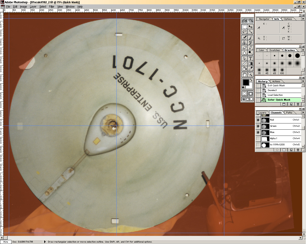
In trial #1, I adjusted the image after the Hugin optimization step so that the X-Y axes were perpendicular.
I found the lettering "baselines" and the horizontal control lines for the rectangular lights were 0.6 degrees out of perpendicular - except...
EXCEPT that the lights control lines varied and were not the same!
What was worse, those lights were not symmetrically placed left to right.
Could the model makers really have been off by that much?! I have trouble believing that.
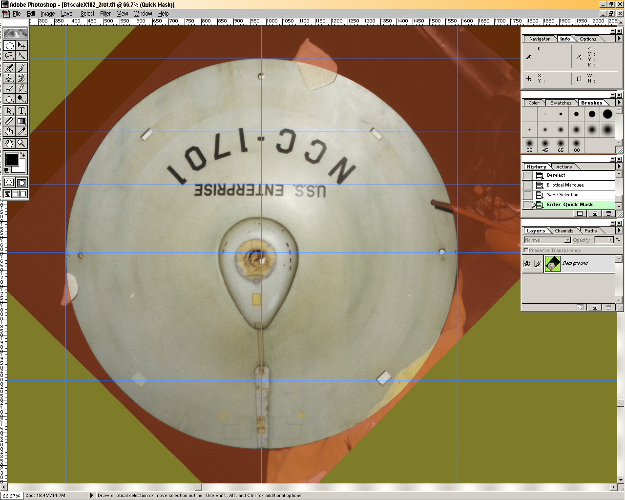
So in trial #2, I did not make the image adjustment after the optimization step and found that the baselines and control lines were nearly perpendicular to the saucer centerline.
What's more, the lights lined up with each other very well, left to right!
The supposed X axis on which the running lights lie was off the perpendicular with the Y axis by only 0.6 degrees,
and to my mind, well within reasonable deviation when laying them out across the full diameter and across the upraised bubble of the saucer.
I think trial #2 is the more accurate solution.
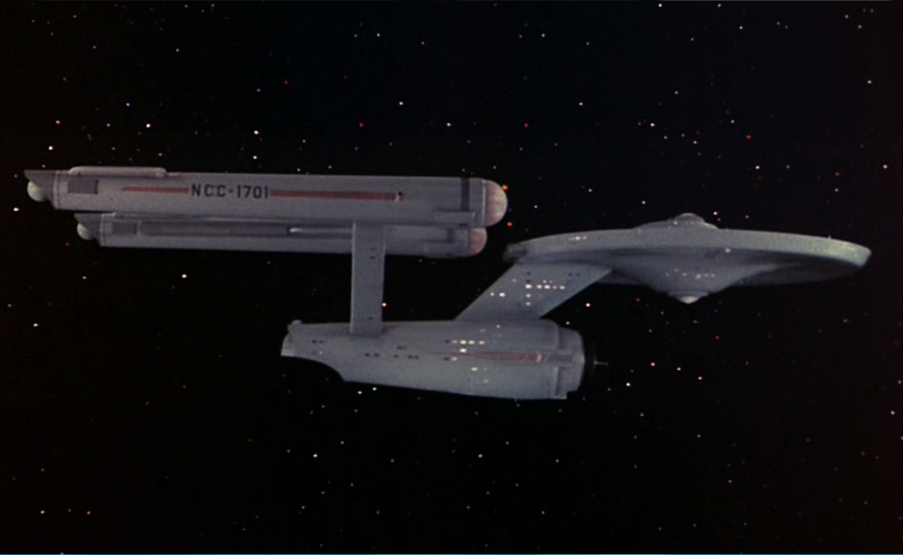
Side view (static camera & model - image panned across screen) in Doomsday Machine
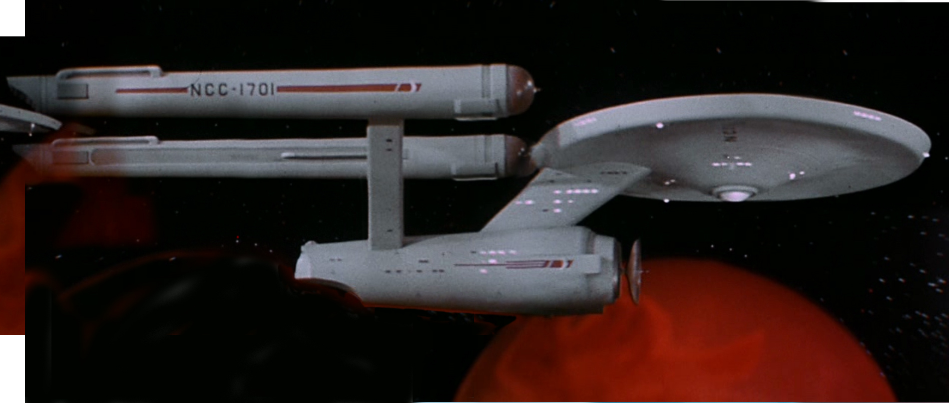
Side view (static camera - model moves) constructed from multiple screen caps as model paraded by in Gamesters of Triskelion
Side view, 2nd version
Comparing the 1st constructed shot to Sinclair's elevation with my own tracing superimposed
Corrected comparison
Closeup showing accuracy
note dashed circle
Sketchbook corrected top/section comparison
Corrected 3-view
Corrected hangar
Sketchbook corrected hangar
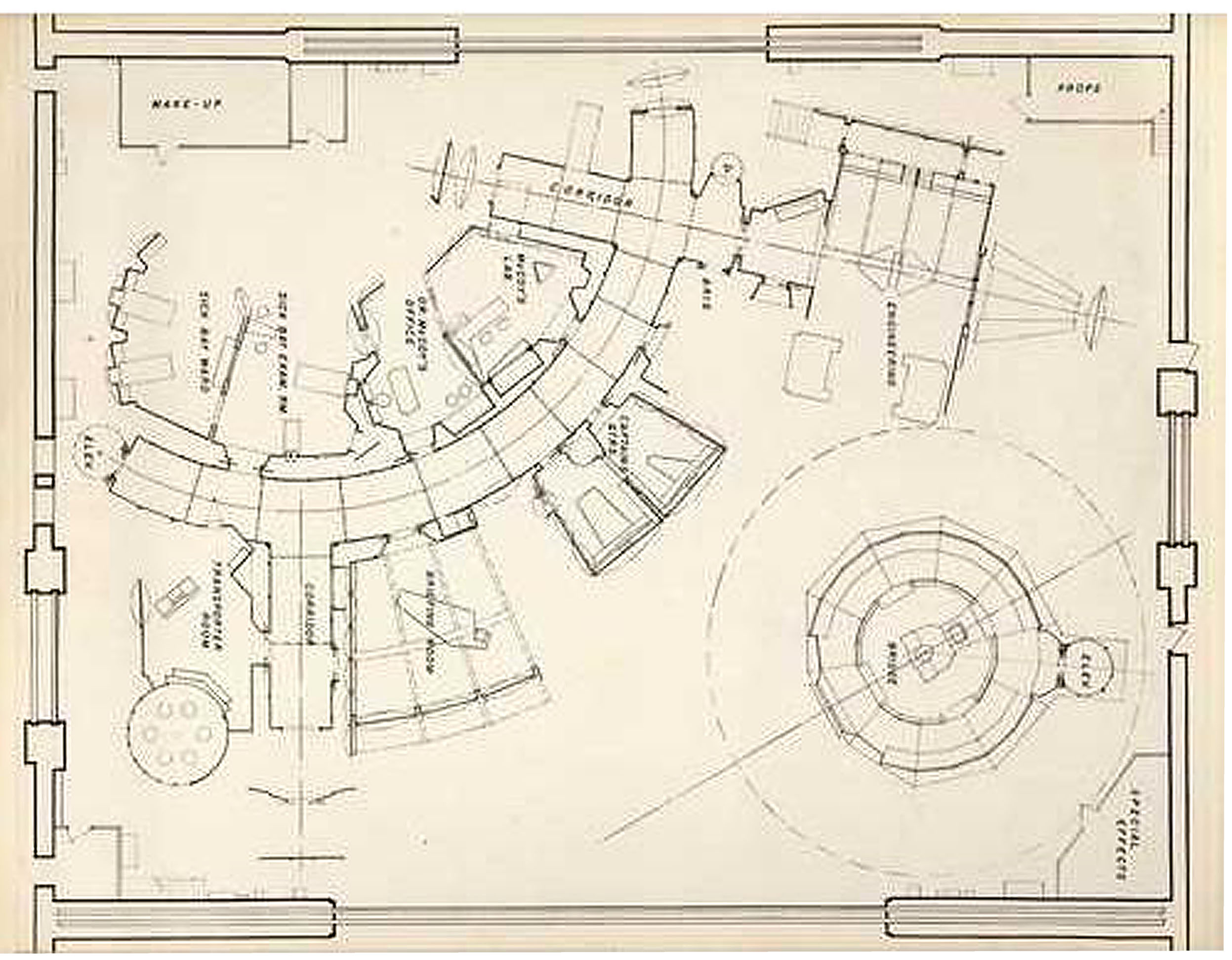
Corrected soundstage
Original taken with an Olympus D380 in NASM
Corrected with Hugin after MUCH trial and error.
Note the X-Y axes are off by 0.7 degree.
Original overlaid with grid lines
Trial #1 - Huginized and masked
...then rotated
...and with radial gridding traced
Note that the X-Y axes are perpendicular, but the lettering and rectangular lights are off about 0.6 degrees
Trial #2 -
Original corrected
You want THIS one!
...masked
...and rotated. Note that X-Y axes are off by 0.6 degrees,
but the lettering/lights are 90 deg. to the center line.
I vote for THIS version!
Remember when examining my Huginized images...
...only features on the same plane are in correct relationship to each other.
If you are looking at features on a plane above or below the one that I set to be corrected, they will be correct only in relationship to other items on that same plane.
BUT they will NOT be in correct relationship to features on any other plane.
By "plane" I mean planes perpendicular to the viewer at any distance receding from the viewer in the Z-axis.
Happily, although one cannot measure features between planes, each plane along the Z-axis is proportionally correct and with the same proportions as all the other planes in the Z-axis.
Therefore, the planes can be scaled to each other if a known relationship exists between the two planes of interest!