Hangar Deck . . . Single View Reconstruction by hand
There are a few very good reference plans out there for the original starship NCC-1701 USS Enterprise.
Alan Sinclair has one and Charles Casimiro has another.
They do differ slightly as David Shaw showed here.
But how is one to know how good they are, and which one is best for what detail?!
So, I guess I just had to find out for myself. Six years later and I am getting closer.
And on the way I wanted to resolve how well the hangar deck could fit into the model.
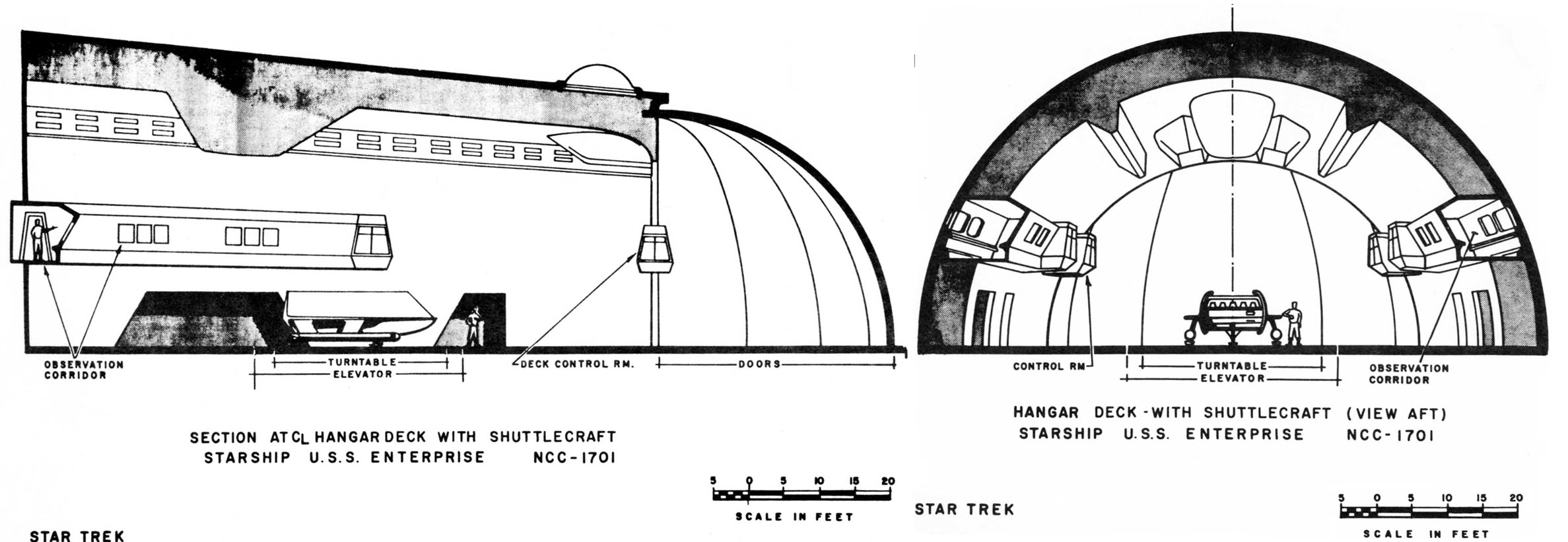
I began by taking Sinclair's side view of the engineering hull and fitting a hangar deck into it as per Matt Jefferies' drawings found in the The Making of Star Trek (TMOST).
I chose Sinclair's drawings because it was used to produce a decent paper model of the TOS Enterprise, found here and a repaint of it here, which I could adapt.
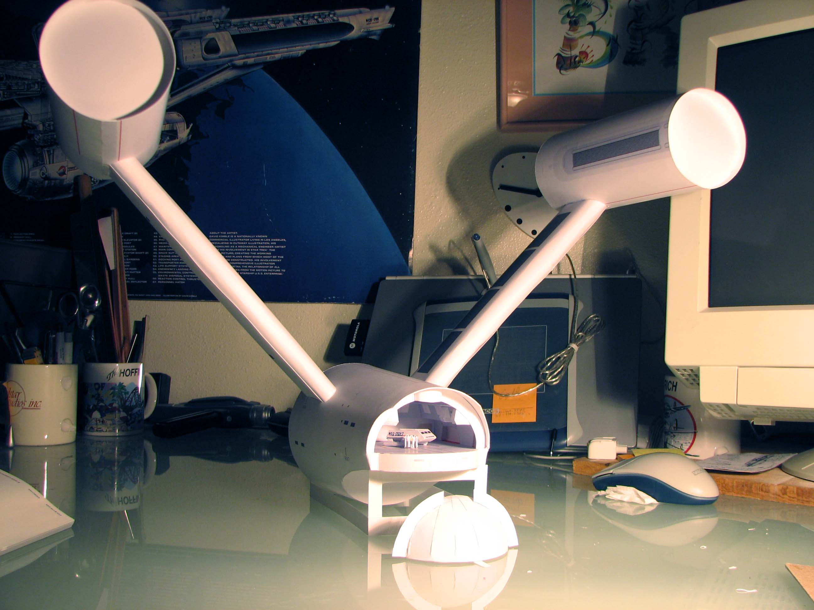
I quickly decided to mock it up in cardstock.
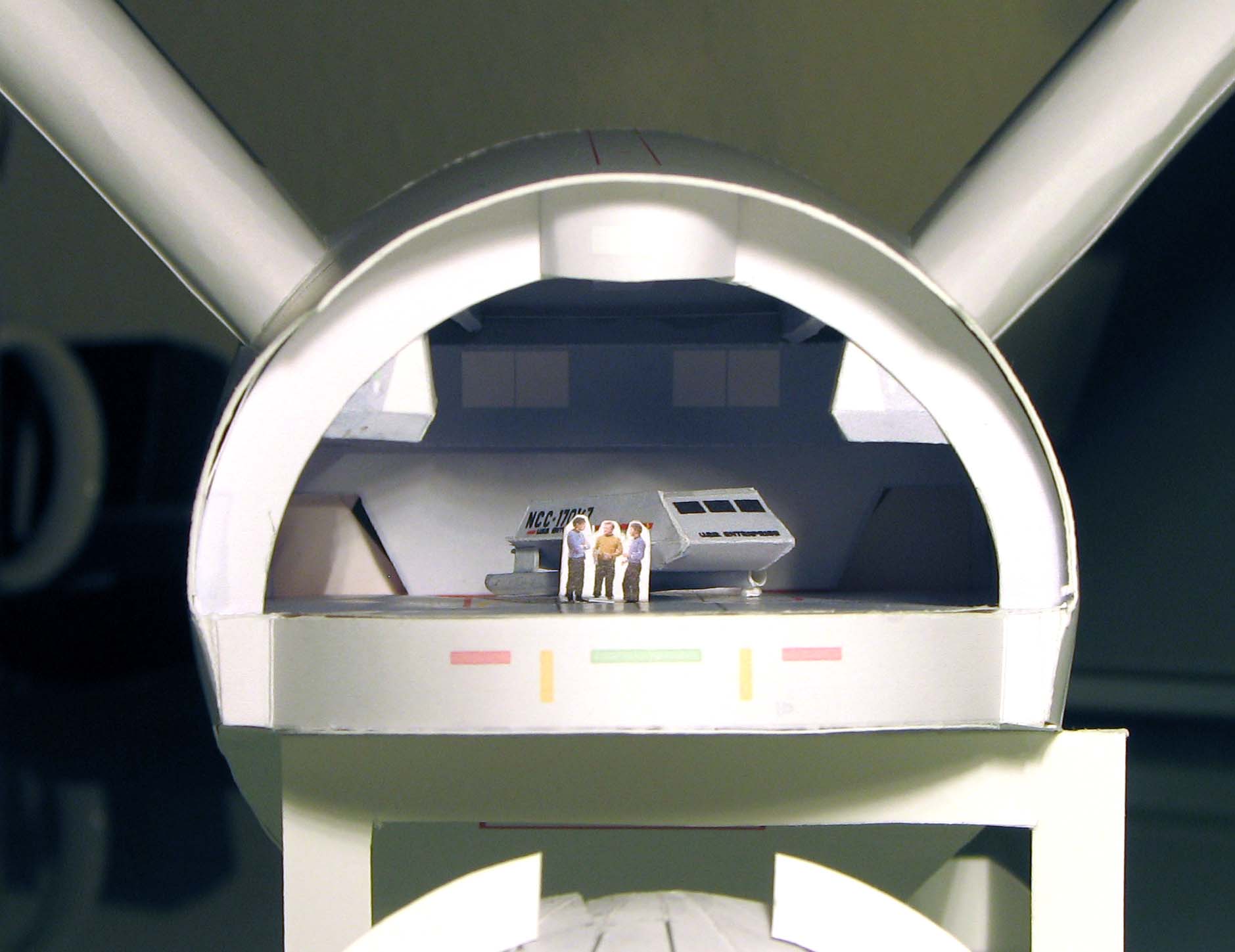
I made one experimental decision...I would make the ceiling a constant height, as though it were Quonset hut shape.
It was easier to do and I wanted to test if that was indeed what was really done on the filming model, and if it would work in the space.
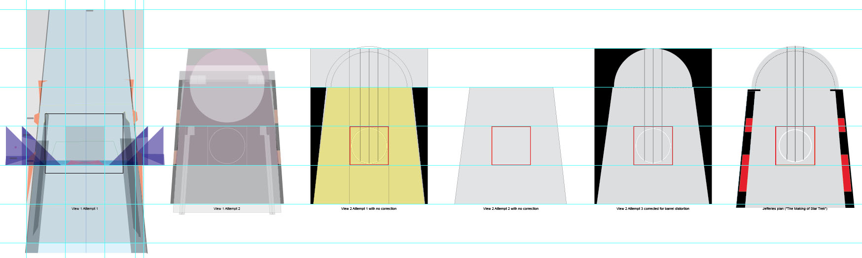
The series on the first row is that model. The first image shows the space I decided it must fit into.
The scale ended up at 1/192, which as it turns out is half the size (twice the scale) of the 11-foot Enterprise filming model.
I concluded that the constant-height ceiling was not accurate, i.e., it did indeed slope down stem to stern.
So back to the drawing board, a digital one in this case. I began relearning how to create a three point perspective.
My high school drafting served me poorly.
I followed the steps, but could never understand how it worked!
I searched books and the web and discovered this website, Handprint, whose approach was thorough enough for me to work it out (weeks later).
Learning how to create a 1-, 2-, and 3-point perspective from elevations allowed me to work backwards from a perspective (read: photo) to elevations (read: plans).
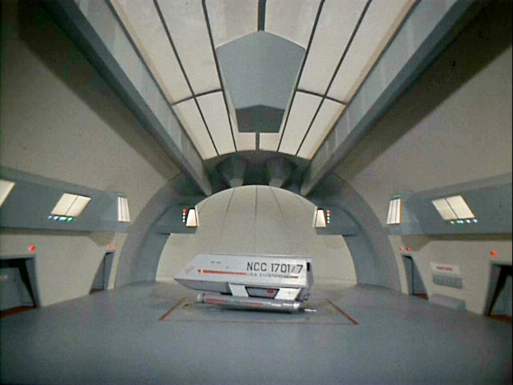
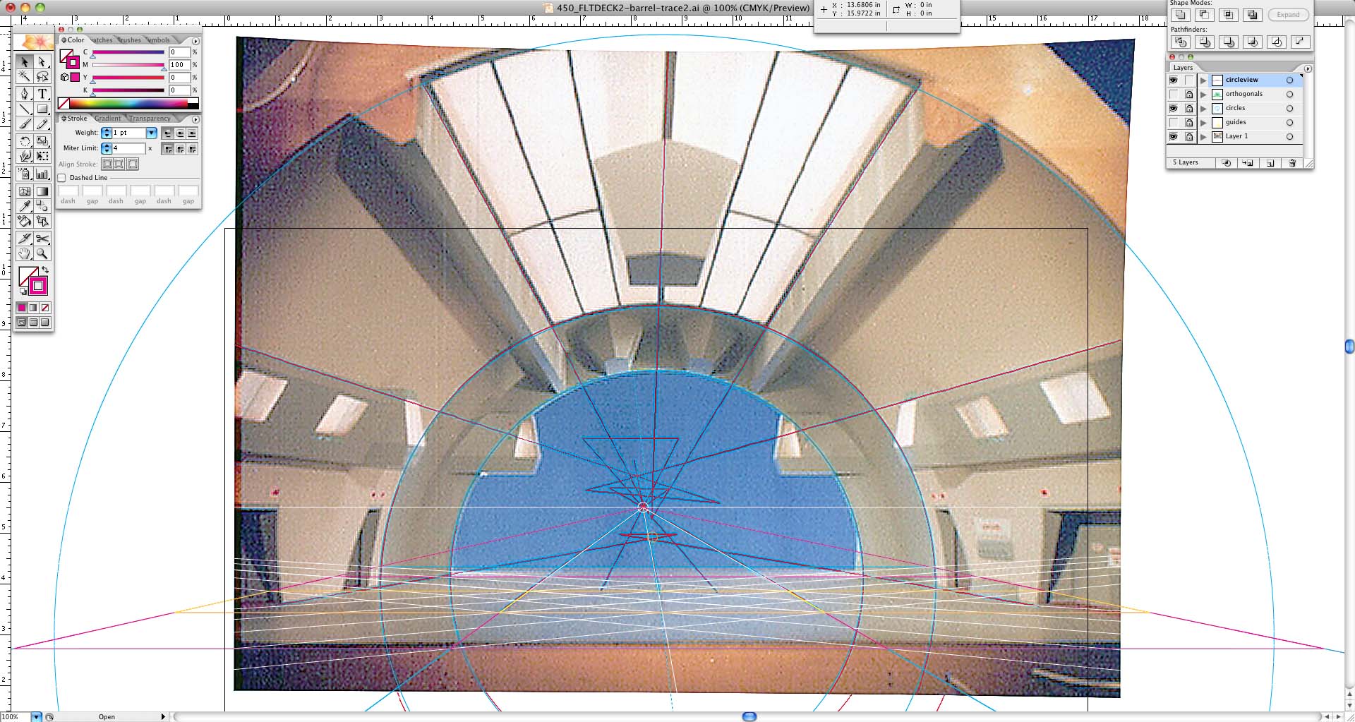
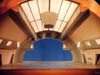
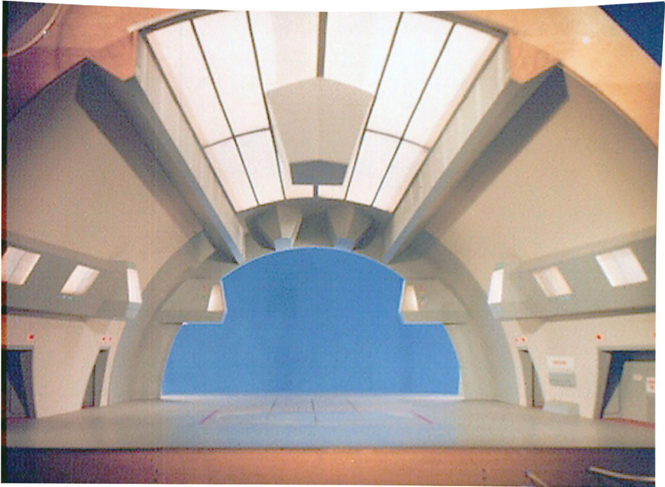
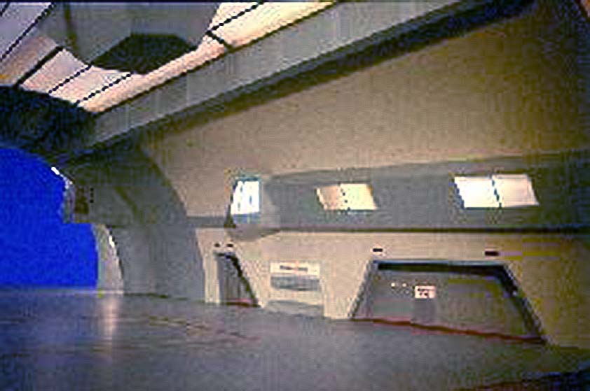
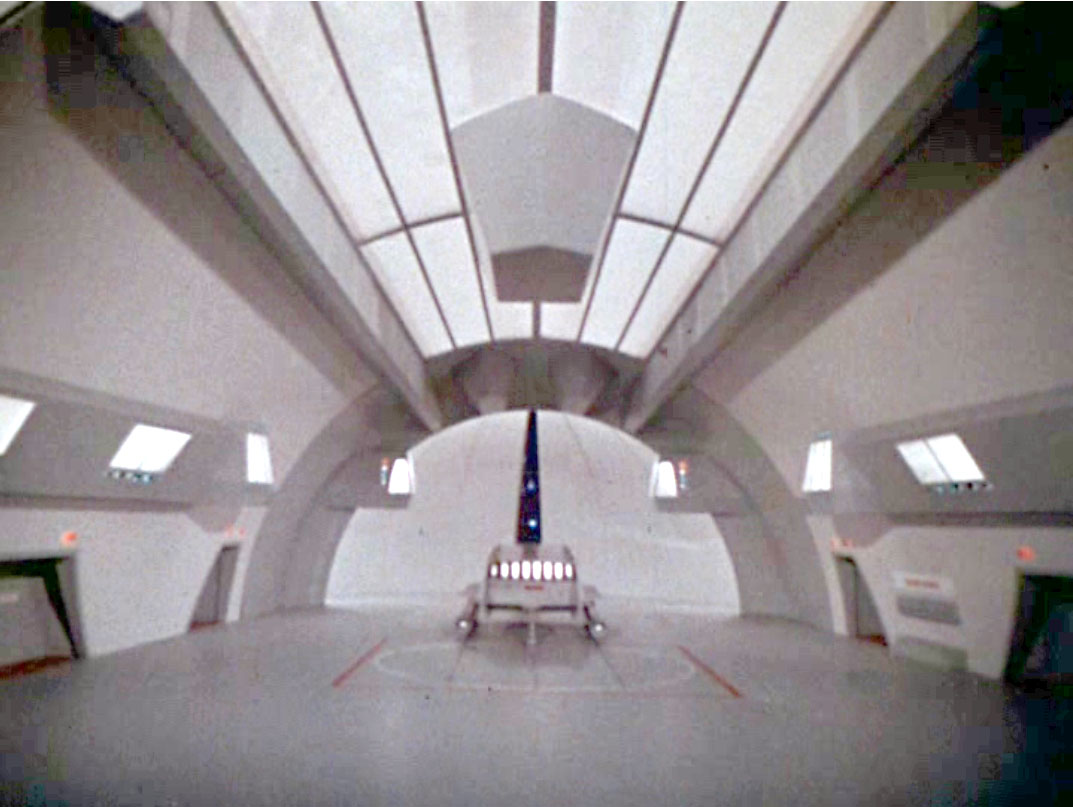
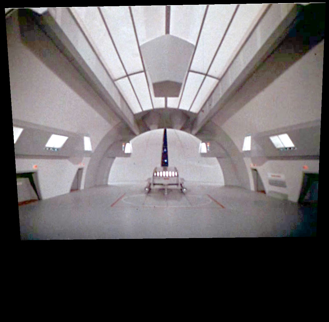
My first effort used a screen cap of the famous hangar scene.
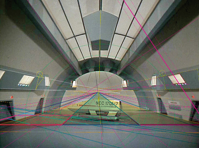
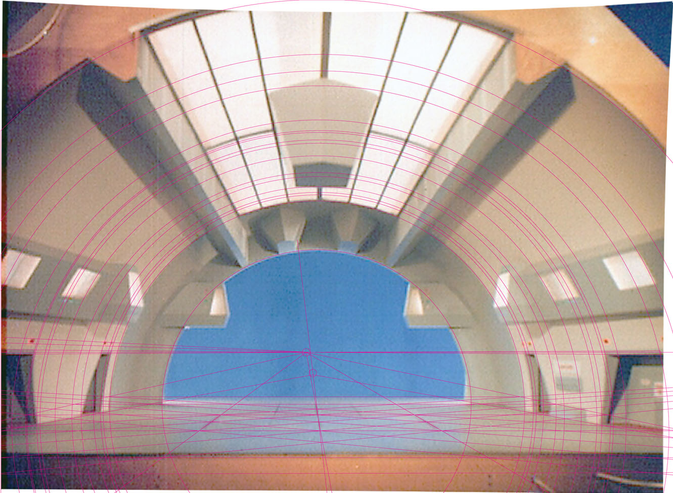
The hard part is establishing accurate edges and finding consistent vanishing points(vp's), consistent with each other.
Four times I traced the photo to establish the vp's; each time being more accurate and pickey about placing my lines on edges.
But I was finding inconsistencies left to right with symmetrical landmarks.
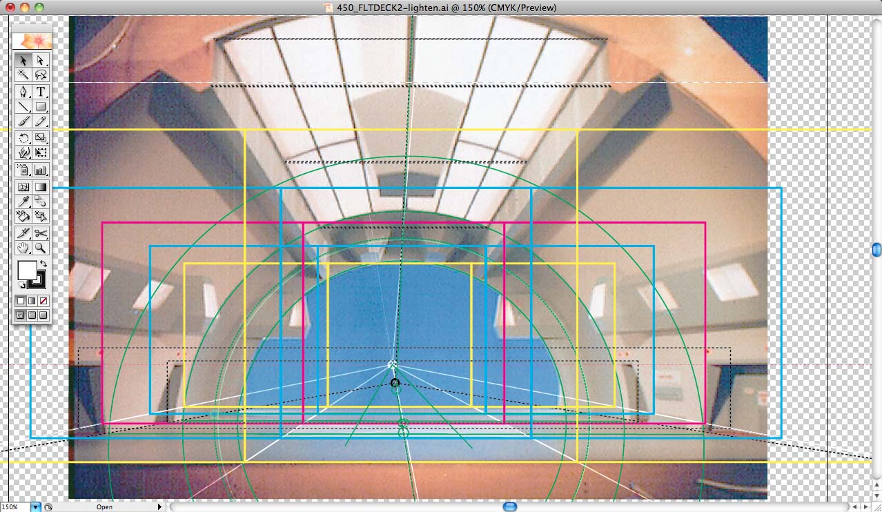
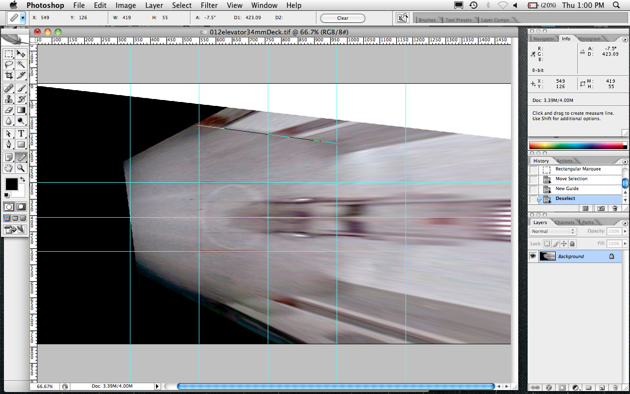
The 2nd and 3rd photos show some of my linework and the final grid, which is based on the size of the red-outlined elevator.
The hangar turned out to be about three grids deep with the elevator about on center.
But I could not be sure how far forward it came because it was cut off in the photo.
Then I found Richard Datin's website, the maker of the model, on which there was a photo showing part of the front frame.
My first efforts led me to believe there was some camera pincushioning distortion to it, so I manually tried to correct for it in Photoshop.
That meant I purposely introduced some errors attempting to correct for bigger ones (Hugin would later overcome those).
Another problem was the viewpoint is rather low so that one cannot be precise about distances in depth on the deck itself.
But conversely, dimensions in height would be very accurate just as is.
After about five iterations finding the various 1-point perspective control lines and vps, plus a couple of side forays with a couple of other images I found on the net,
I settled on a pretty tight set of lines to the central vp.
And 1-point perspective was supposed to be easier I thought to myself. HA! Easier, yes, but not easy.
Given all the trials and frustrations, I concluded that there was some variation, but Datin's view corroborated the screen cap findings.
Which brings us to the last row, my summations.
First is Jefferies' drawings that I have corrected so the cross-sections are indeed a half circle instead of elliptical.
I created a plan view from the corrected drawings.
Then I simply compared my major stepping stones to Jefferies.
And then I compared my best effort from Datin's photo to Jefferies, scaling it so the depth matched.
They are very close, close enough to lead one to believe that Jefferies drawing was used to create the model.
But knowing the distortions I introduced and the variations between all my attempts, I was not satisfied to declare it done.
I needed to start without the distortions. But even more, I needed a better tool.
Enter Hugin!
(1st attempt)
Plotting out available space
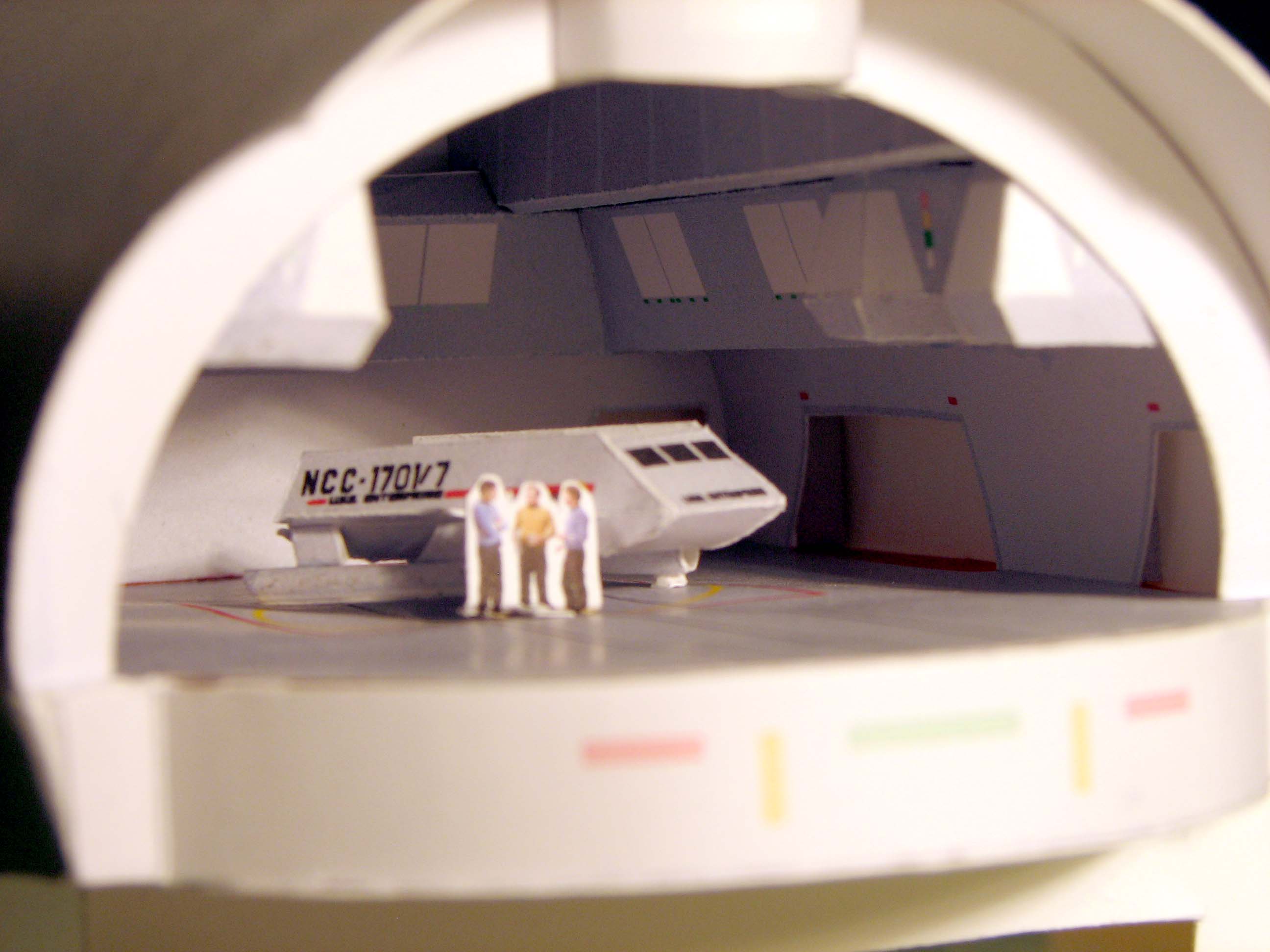
1st attempt, end view
...close-up
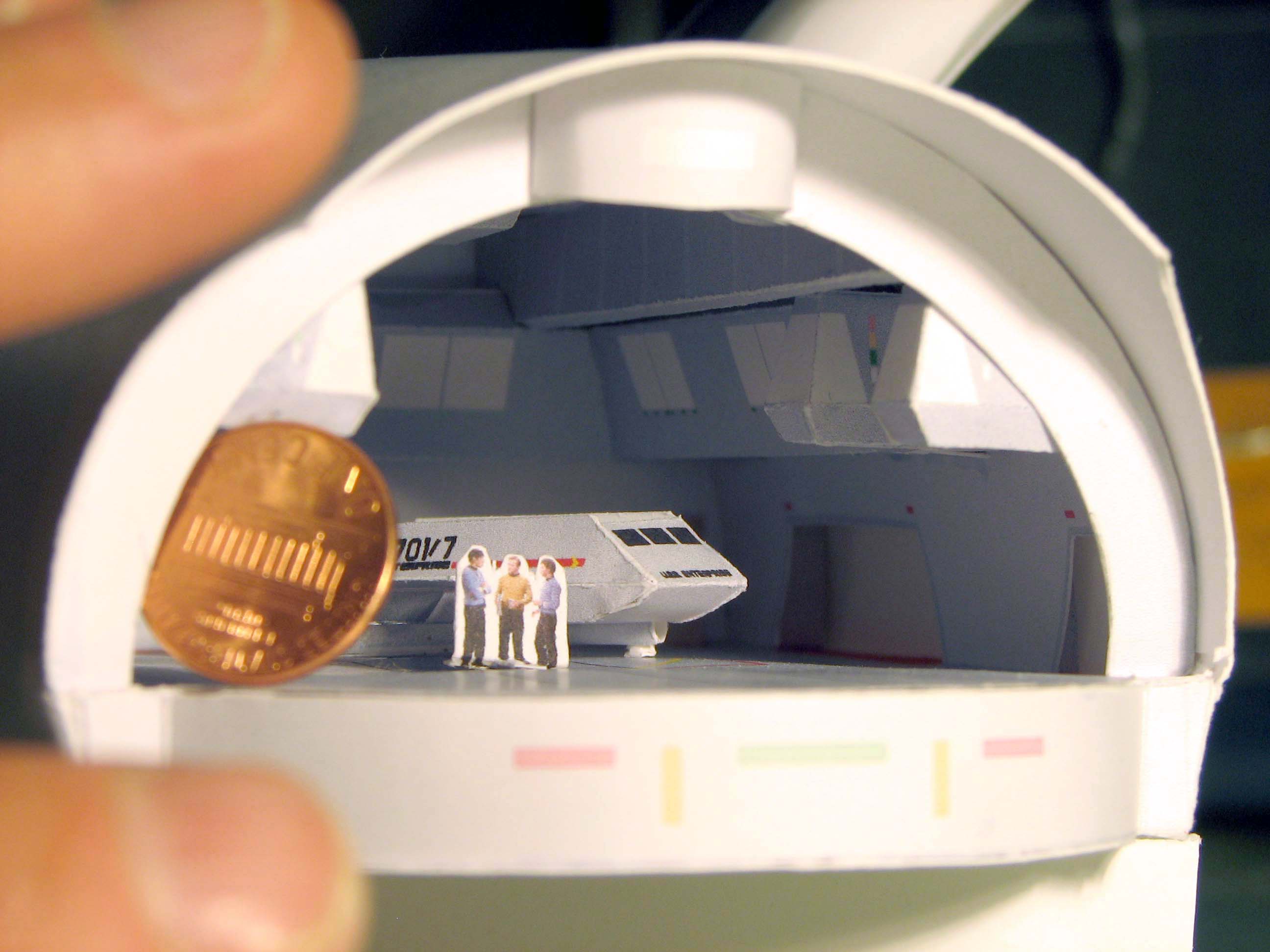
...a penny for scale
...the entire sectioned model
(2nd attempt)
Screen cap of the studio model
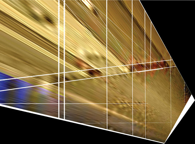
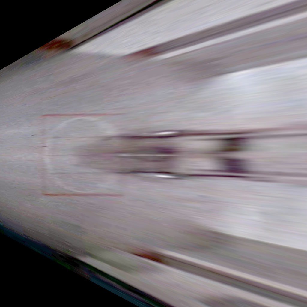
...determining the perspective
...gridding the scene
(3rd attempt)
Click image to go to source
...determining the perspective
...gridding the scene
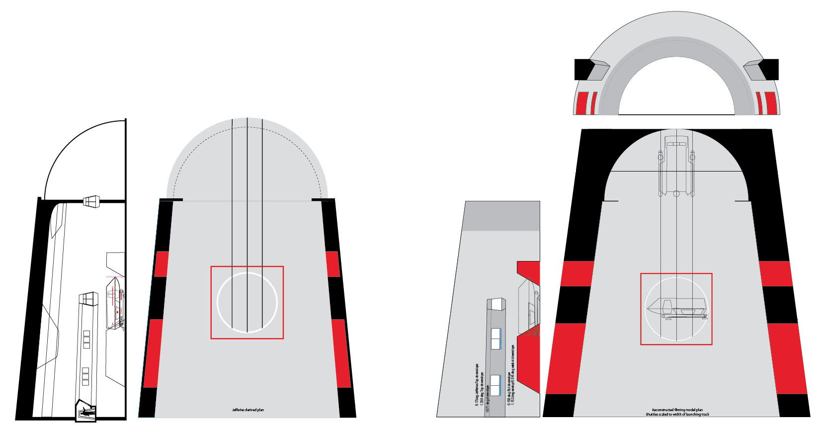
Matt Jefferies' plans (TMOST) corrected so ceiling is semicircular-not elliptical
Comparing floorplans of my different attempts
Comparing Jefferies' 3-view with
the reconstructed plans...
TBD
...and how I adapted them to the available space in the 11 ft. model.
Hangar Deck . . . orthographic correction by Hugin
I worked with many images, but the three most helpful are shown here.
Two are from Richard Datin's StarTrekMan website
and one is a screen capture from Journey to Babel.
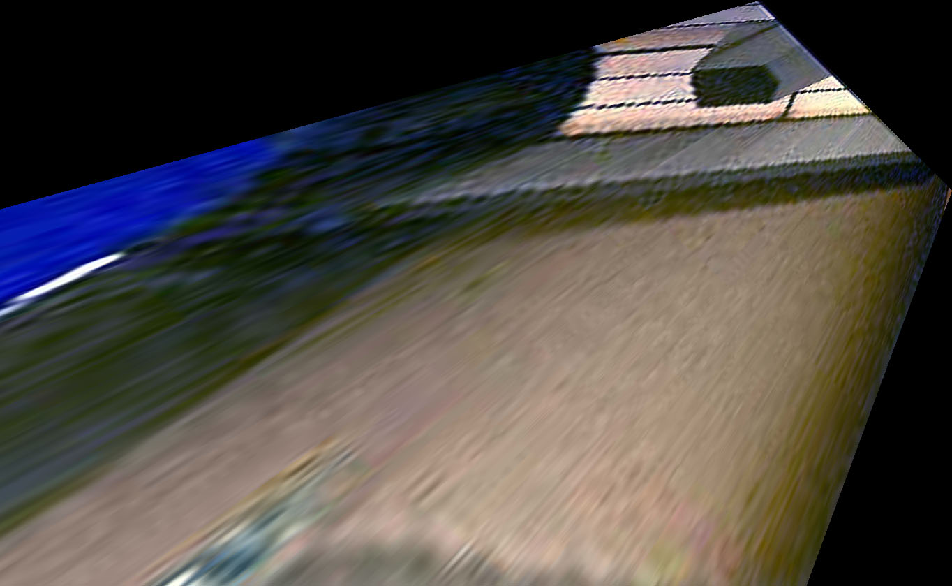
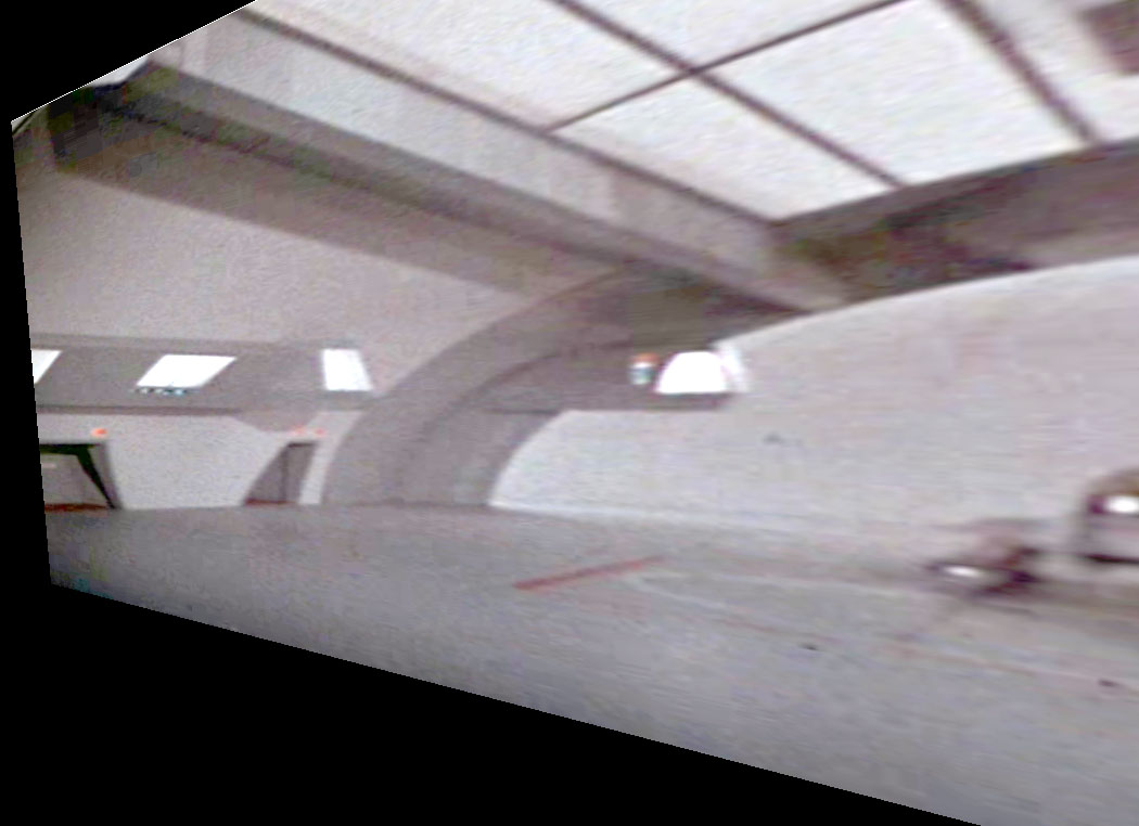
I begin here with the Datin photo I have come to love and hate.
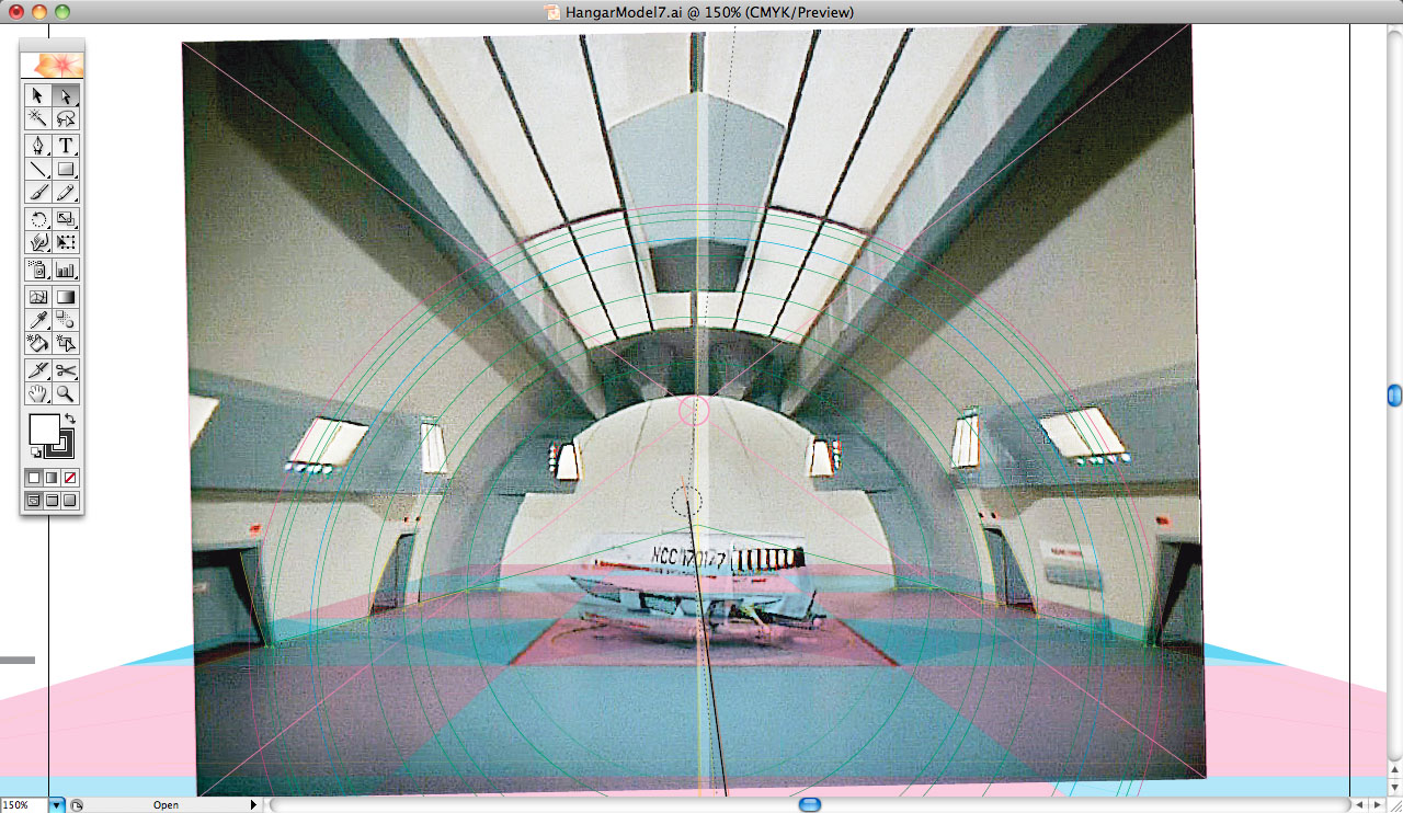
I have played with Hugin's controls for yaw, pitch, roll, and focal length enough to know how to drive it, so to speak.
One thing I learned to do was create a version of the image with my control lines superimposed to aid in aligning the image.
I also sharpened the image and super saturated it to make details of interest stand out.
So I have two image of the same pixel dimensions: one with and one without control lines.
I use the control line version first to dial in the proper viewing angle to give me a 90 degree look-down plan view of the deck.
I trace the control lines to lay out the horizontal and vertical lines of the plane I want to orthorectify (the deck plan).
It is still a trial and error process once I get close, requiring me to make slight adjustments (tenths and hundredths of a degree),
and checking the results in Photoshop where I can determine if my horizontals and verticals are at rights angles and if what should be a square is so.
Important -- to make this work, you will need to have a feature with a known aspect ratio or dimension in both axis. Squares and circles are best.
In this case, it just so happens that we have both with the elevator: a square outline and a circle in the center.
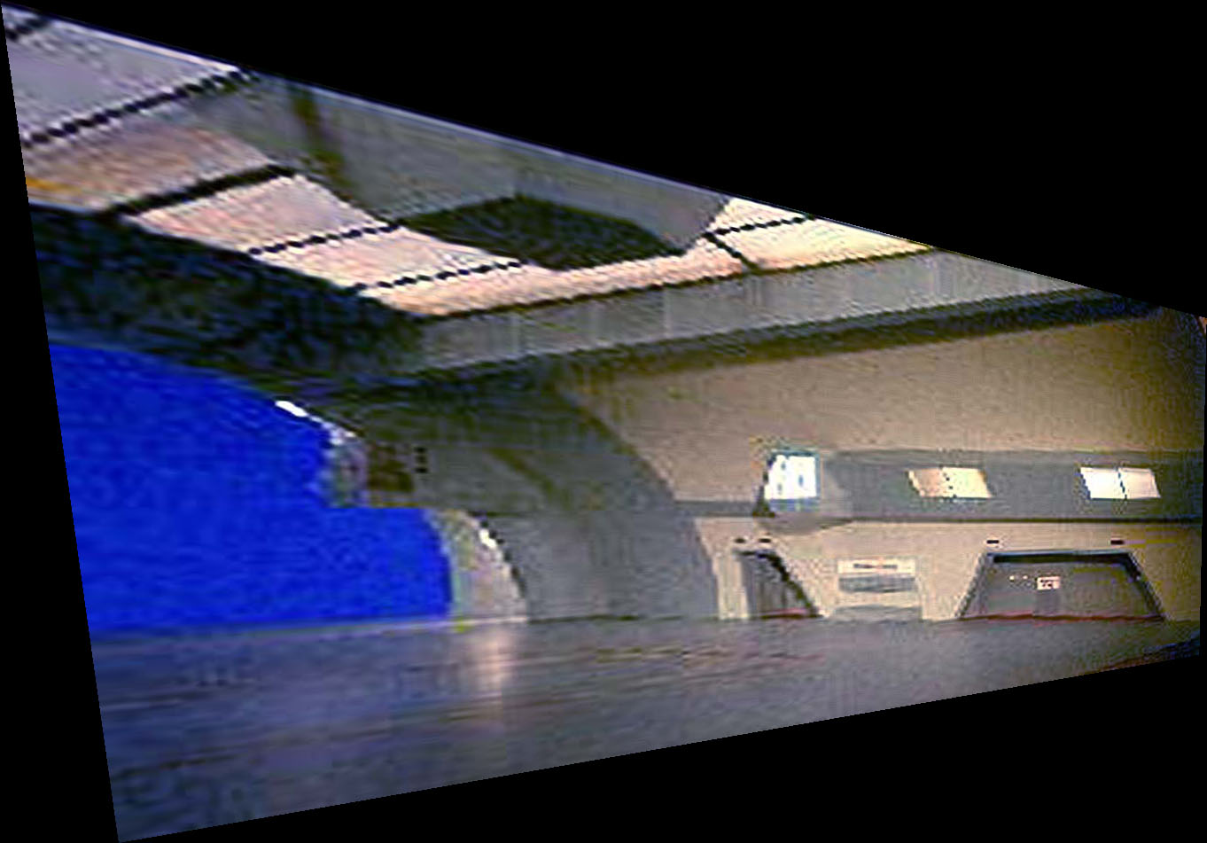
Once the 90 degree sweet spot is found, then I rotate 90 degrees back to the original viewpoint, which has now been ortho-corrected and the central vp found.
From there, I can rotate to either side and up as well, or to any angle in between.
Because the deck is actually a trapezoidal shape and not a rectangle, the sides of the trapezoid could be found in the look-down view.
It turned out to be between 7 and 7-1/2 degrees off vertical.
So rotating right, left, and up 82-1/2 to 83 degrees gives one a view that is parallel to the side wall.
But be aware of one thing. . . because the hangar is shaped like a truncated cone, the horizontals are not parallel and, therefore, not to scale vertically in the Hugin views!
They vary as a function of their distance away from the chosen plane, which in this case is the plane that intersects the deck at the point where the side walls intersect the deck.
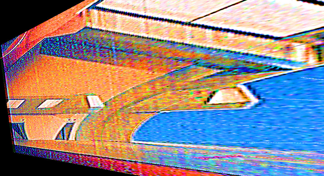
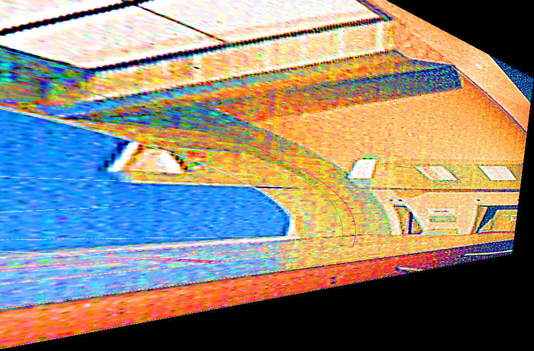
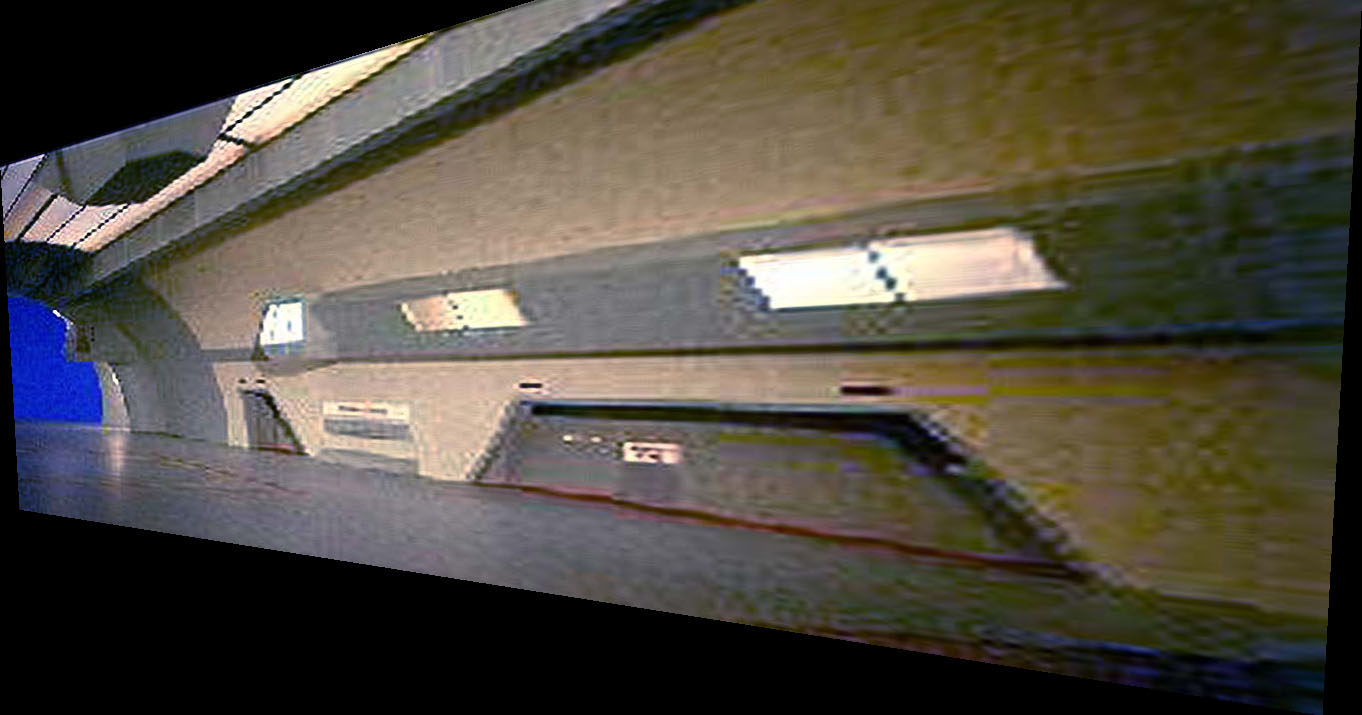
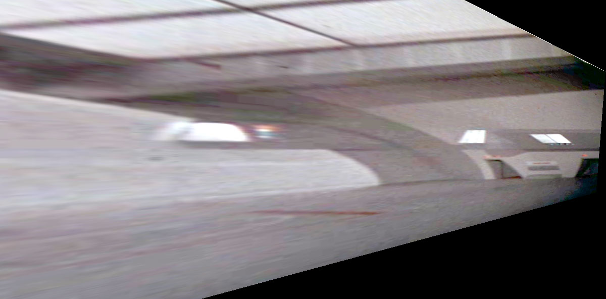
The second set of images is also from Datin's website. It is a 3/4 view into the model looking at the port wall.
Same technique and similar results.
Interestingly, the focal lenth was equivalent to a 35mm lens on a 35mm camera.
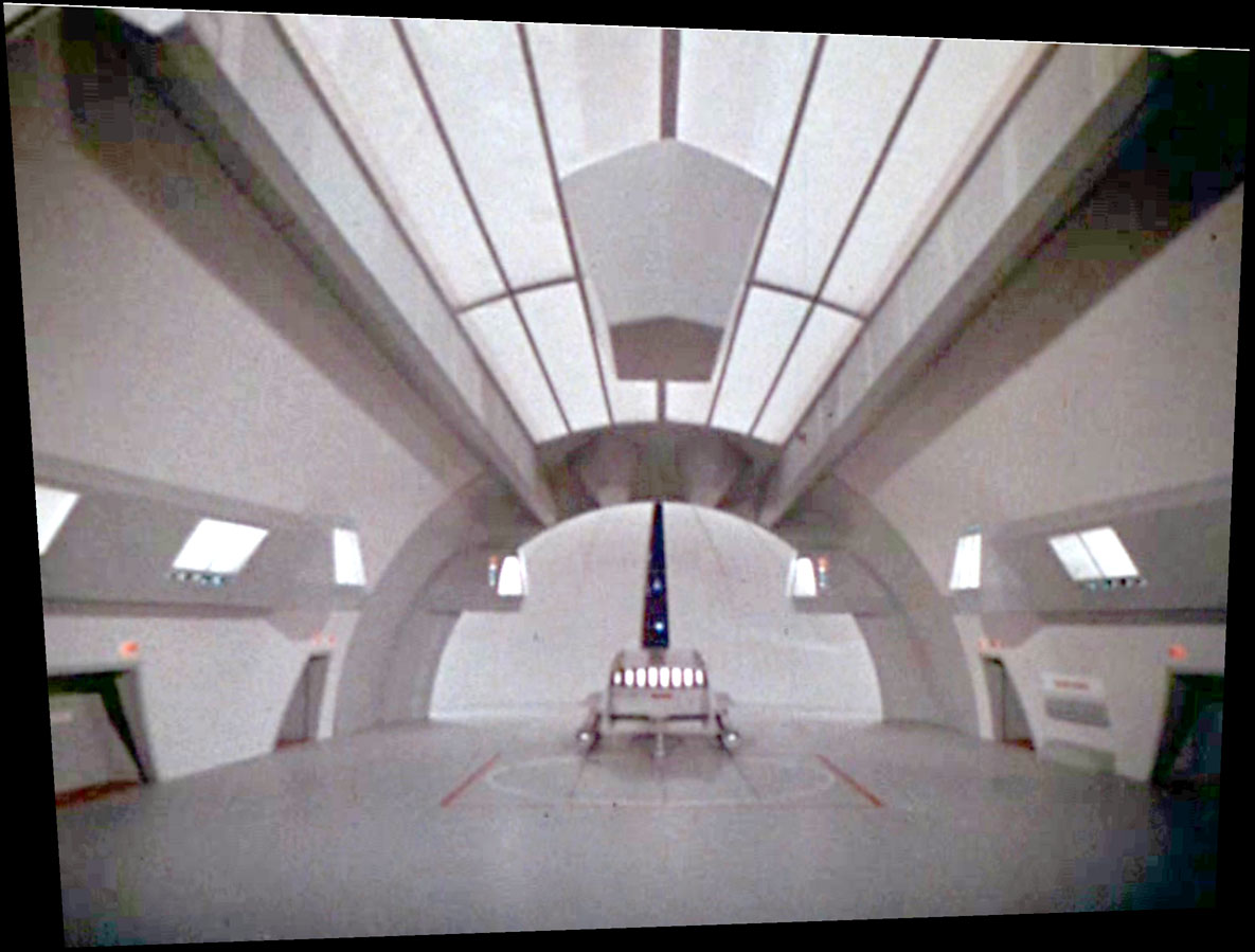
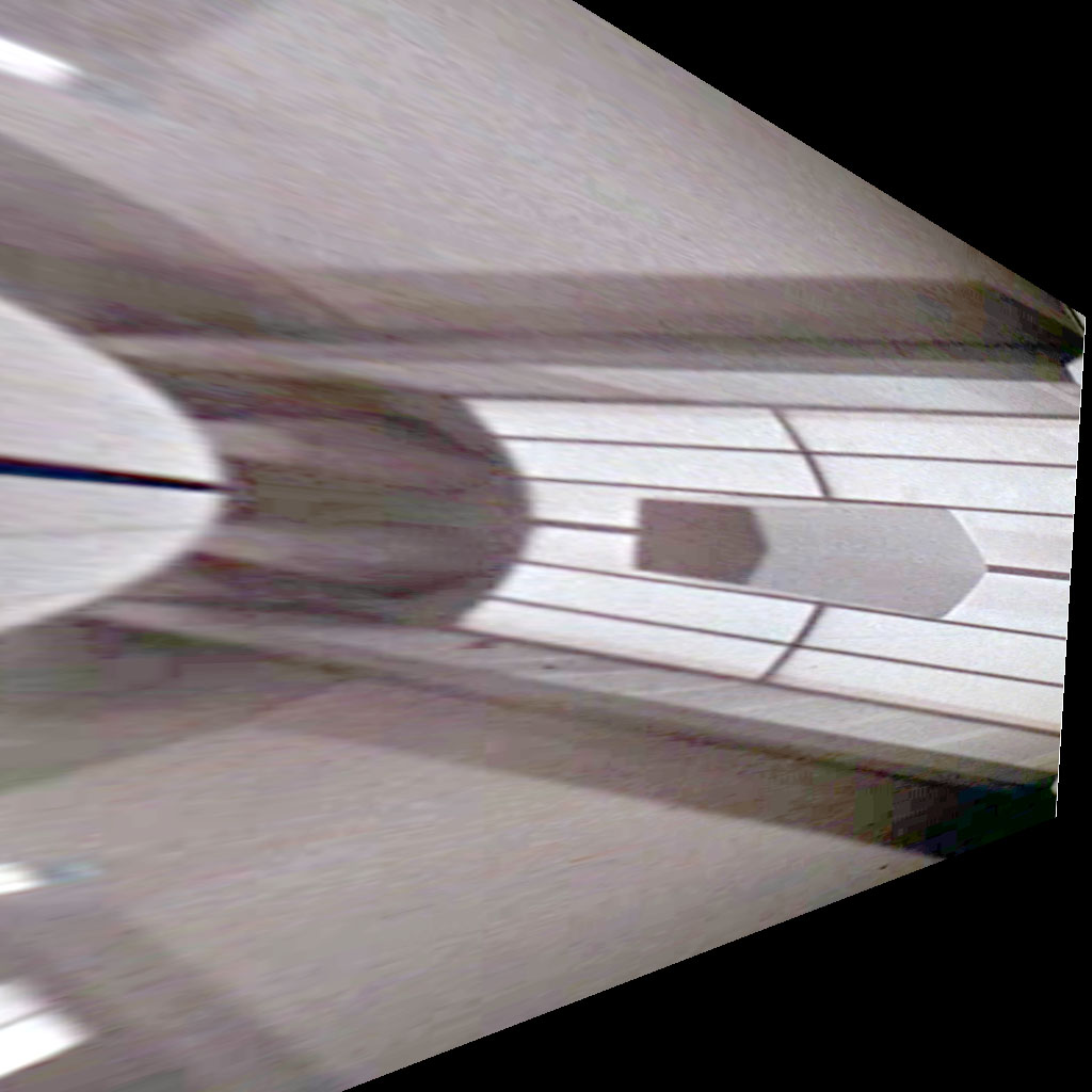
And the third set returns to the original screen capture, again with similar results.
The angle of the side walls averages to about 7.5°, assuming the fuzzy elevator outline is a square.
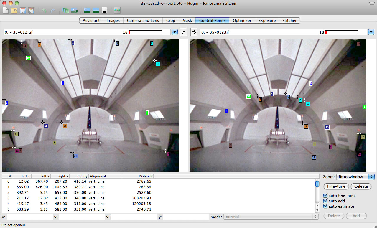
The fourth set uses the original screen capture, but this time, I chose a different set of lines to correct to.
Since this is a one-point perspective, I set my "vertical" control lines to the edges converging to the vanishing point (the z-axis) and my "horizontal" control lines to the x-axis.
I assumed (a big assumption!) that certain points in the x-axis would be symmetrical, i.e., not different in their z-axis coordinate.
The first image shows the point pairs I chose.
The second image is the "optimized" (or corrected image) optimizing for x, y, z, and view point in Hugin's optimization menu.
At this point I rotated the view to look down on the deck.
I then fine tuned yaw, pitch, and roll to obtain a rectangular flight deck outline.
In order to do that, I created a heavily sharpened version of the base image (settings 500/8/2) and a super-saturated version (HSL with S at 50%).
This is trial and error: changing y-p-r, save file, check for parallels in Photoshop, repeat.
I needed to scale it either horizontally or vertically to make the outline into a square - about 86%.
The third image is the fine-tuned and disportionally scaled deck view.
For a check, I rotated the pitch 90% back to the beginning viewpoint and check for the image center compared to the vp center.
There were very close, closer than what I obtained in previous trials using the earlier control points.
So close in fact that I was able to shift my by-hand vp to the Hugin vp and it still worked - maybe even better than by-hand!
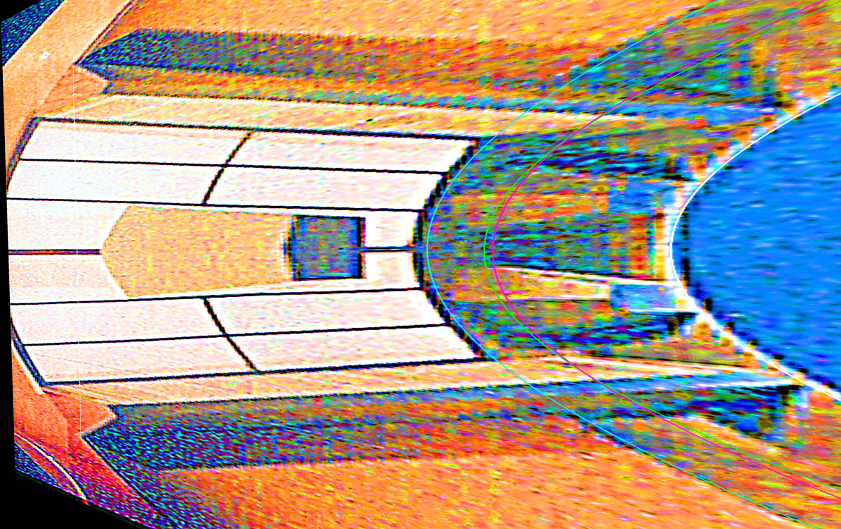
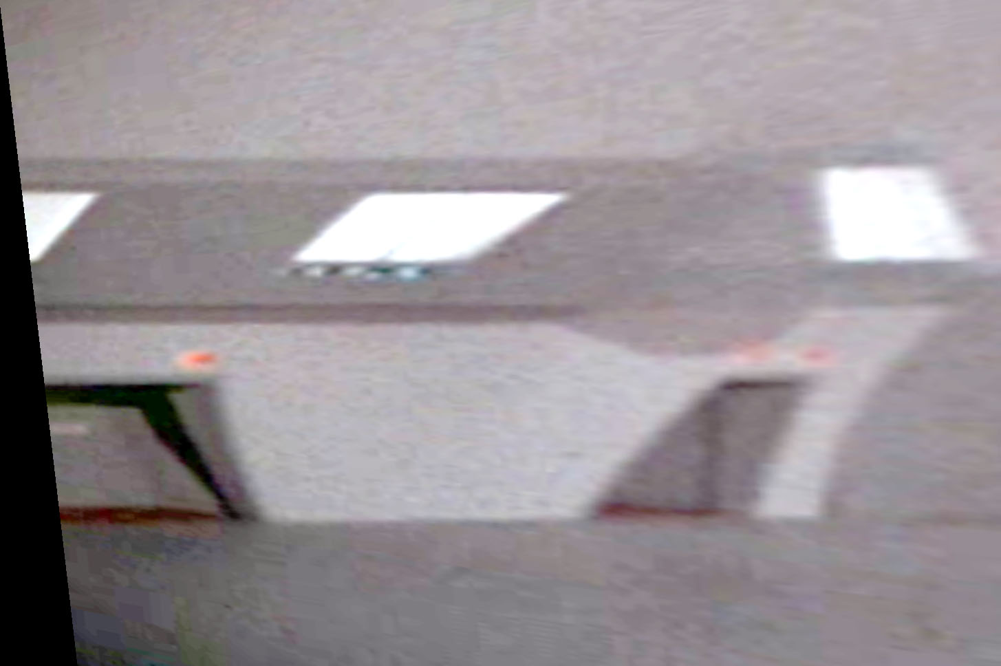
The fourth image is the starboard wall.
To arrive at this, I worked from a tidbit I found in Gary Kerr's BBS descriptions about the hangar model.
He noted that the overhead galleries on the model were actually a constant height and were a constant height above the deck, unlike the TMOST drawing.
I aligned the wall-to-deck intersection and the gallery horizontal edges to be parallel.
The resultant angle turned out to be 84 degrees off the z-axis centerline, i.e., the deck/wall intersection is 6 degrees canted off the z-axis towards the deck z-axis centerline.
Did you get that? Six degrees - not 7-1/2!.
Which is correct?
I like 7-1/2 because it is easier to construct using a T-square, triangles, and a compass.
It makes more sense when drafting in the days before computers.
Six degrees has to be measured off with a protractor.
You need a good reason to make it six degrees. Perhaps one of you readers of this page can come up with that reason. Let me know!
Datin's photo
With perspective lines superimposed
Flight deck
Starboard side
Port side
Ceiling
Datin's photo
Deck view with perspective lines superimposed
Starboard side-
control points set to alcoves
Flight deck-
based on alcove
End view-
based on alcove
Ceiling-
based on alcove
Screen capture
Corrected by Hugin
Flight deck with perspective lines superimposed
Starboard side
Port side
Ceiling
Point pairs
Corrected by Hugin
Corrected flight deck
Port-side alcoves & gallery


