Contact: Rich Kurz Page content last updated May 17, 2024
The Construction Diary
2021
JANUARY
I started the year (or ended last year) preparing the engine to start.
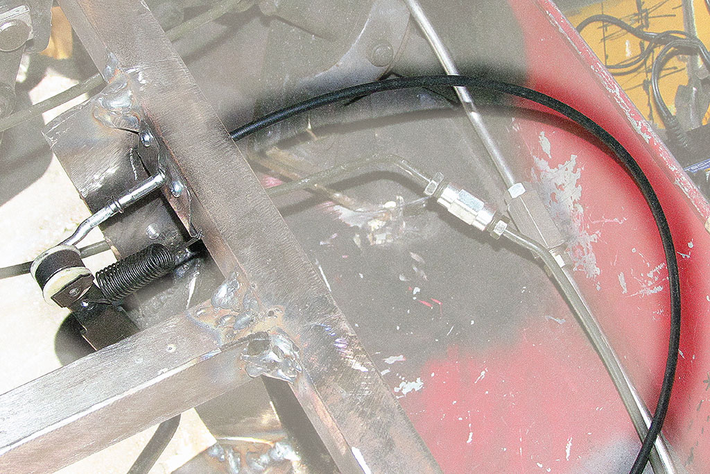
Having dropped the pedal support frame, at last it was time to add the accellerator and run the cable.
I measured how much VW bus cable I thought I needed, cut it, and ran it to an attachment point on my new pedal frame,
and then to the pedal itself.
The pedal is one for the VW Golf I, or Rabbit.
So, interestingly, it is suspended instead of the aircooled VW floor mount.
It works the same (push down on the pedal and it pulls a lever on the throttle) but has to run the cable from above.
The cable then runs down the middle through the shift console to the special opening by the throttle body in the engine compartment.
It works!
FEBRUARY
Work continues on the model, shaping it to the built-in contours.
MARCH
Finally, the weather warms enough to think of actually starting the engine.
I make a starter button, sorta.
Well, it runs the engine as long as I push it.
I connect battery, jump wires to the starter button, run the fuel line to a gas can, and push the button!
The starter turns, but nothing kicks in. Repeatedly.
"Think, think, think" says Pooh Bear.
Ahhh! Check to see if I have a spark!
No, I don't!
Run a wire from the ignition coil to the starter.
Push the button, and it catches!!!
But after a minute, white smoke comes out of the back (by the clutch housing) of the engine.
This is not right. Turn it off and try again.
Again smoke, but I let it run to warm up.
Also the accelleration is sorta rough and does not make high RPM.
For the next few days, I ask around about how smoke could be coming from the clutch housing.
I fuss with the clutch slave cylinder and even add threading to the rod to allow more adjustment.
The wheels had been spinning when the engine ran - rather, one would but not both.
If I put my foot on the brake drum, I could stop it from spinning, but then the other side would spin.
The slave cylinder adjustment did seem to stop the spinning, but the clutch pedal now required heavy effort.
Very odd for a hydralic clutch!
After futzing with the clutch, I start it up again, and again more smoke.
But this time I look UNDER the engine.
And sure enough, I see an oil leak onto the exhaust pipe.
And the dripping oil is green in color! Something to do with break-in oil, I guess.
This is instructive that there is air coming UP from the underside of the engine.
I thought the shield plates were suppose to keep cool air passing over the engine,
but here hot air is coming BACK to the top of the engine!? I will have to noodle that one out.
The leak originates from a push rod sleeve.
Research confirms that this is a common source of oil leaks.
So I get new seals and intend to repair it myself.
But not right away.
Abruptly, in mid-April, work gets busy after a slack year.
FEBRUARY-MAY
Work progresses on the model and it begins to really look like the real car!
Loveland is the home of numerous casting founderies.
And over the years, many sculptors have settled here to be close to those founderies.
Many sculptors means artist supply stores for those sculptors.
It is there I discovered my answer to the problem of using red or blue insulation foam for carving.
Red and blue foam carves well, but fiberglass resin eats it away.
My model is built using red foam, and my gas tanks use blue foam.
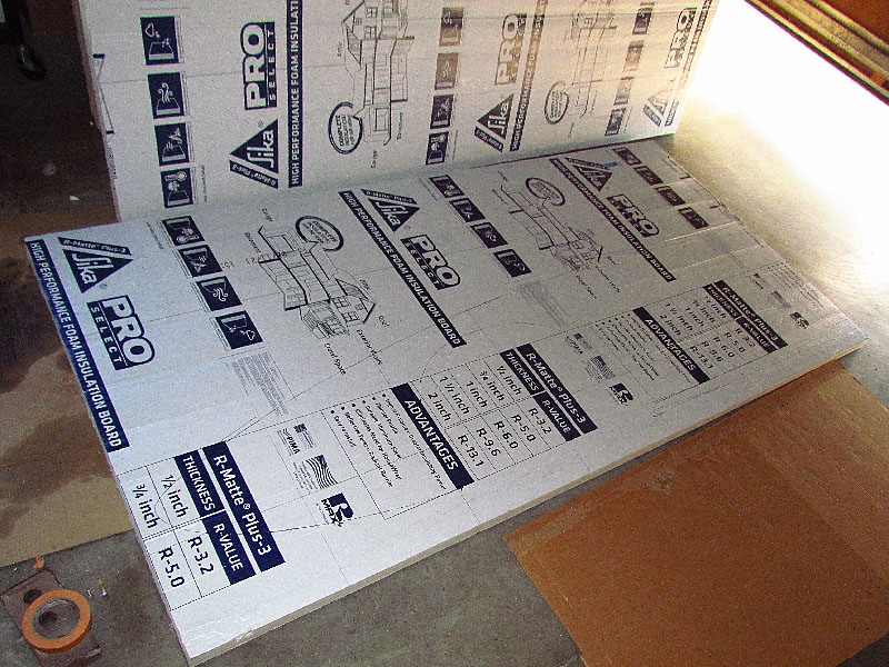
I now know that cream yellow, foil-backed insulation foam is impervious to resin.
My experiments with coatings on red and blue foam all fail to some degree.
What to do?!
While visiting a shop that scales up clay models and carves them in a resistant foam,
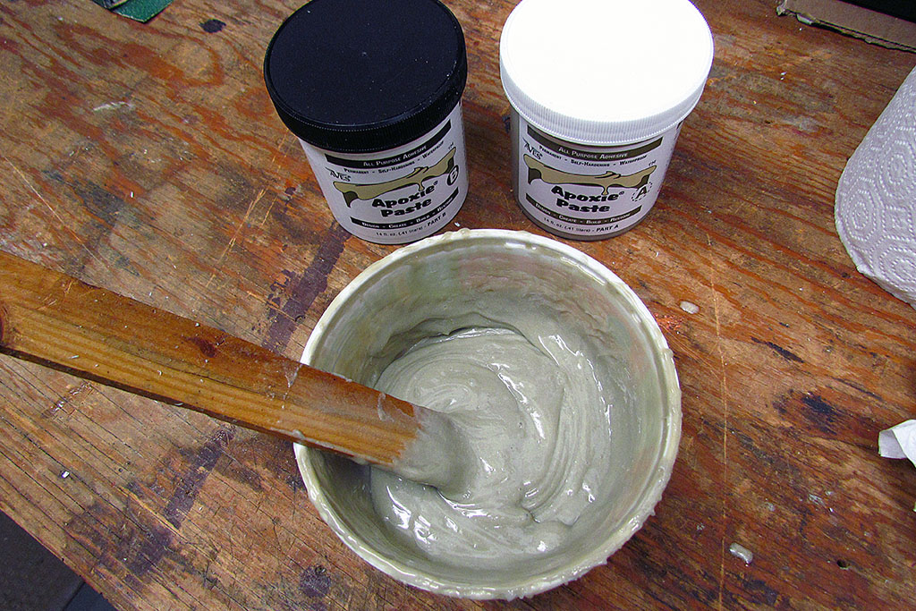
I learn about a product that combines the properties of clay with hard-setting plastic.
It is made by Aves and comes in two useful varieties for my needs.
One is claylike and models like clay for about 1 to 2 hours before it cannot be worked.
It can be worked well with clay tools before setting begins.
The other is a very sticky, gooey paste that is best applied with a paddle or tonge depressor.
It sets overnight to 24 hours. Once set, it makes a hard plastic-like coating, suitable to sand or carve and fiberglass over.
I use the clay version for the model. I spread it out almost like applying a thin sheet of it, and smooth the surface.
The front of the model seems too small, so I build it up at the contours to fit.
But even then, the new contours look too big.
My original half contours turn out to be unworkable. There is no accurate way to support the centerline end.
I invest the time to recreate ALL the contours at full width.
That is when I built up the contours on the model.
But then the centerline contour and the width contours do not meet at the correct heights!!!
This is a BIG problem!
Lots of remeasuring later, I discover the heights of the width contours are incorrect at the base.
They all have to be added to.
This is when my work picks up and I have to set all model work aside.
JUNE
Work is full time for two months.
Finally in June, I get some breaks and turn back to the project.
I got a new used car that needed a radio.
I found a place to check to know if the problem was the radio, or something else.
It was the on/off switch on the radio, so I ordered a new one and had it installed.
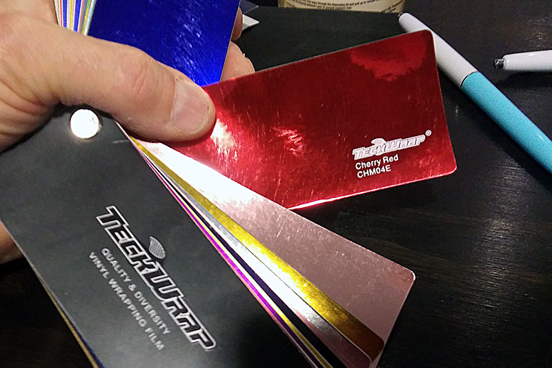
This shop installed radios as a side business, but their primary offerening was car wraps.
Now, the last wraps I knew about were spray-on paints and Kinko-type self-adhesive films.
When the owner showed me the color range they could do, my eyes opened wide.
HERE WAS THE ANSWER TO HOW I WILL PAINT IT!!
You see, I simply cannot afford a $15k+ paint job when I get done building the car.
Here I could get a candy-like finish for $2-1/2k buck!
I told him I'd be back in two years for the job.
One week, there was a slightly sulfurous odor in the garage.
I could find nothing dead, and after a week it disappeared.
A few days later as I walked by the chassis, I happened to notice one battery filler cap was popped off!
And the cap was found about 5 feet away!! And the battery cells were visibly dry!!!
I was immediately educated about what happened.
I had been charging the battery with a real charger - not a trickle charger.
It needed it, but I had left it on for more than a couple weeks.
It seems to have overheated the battery, popping off the cap and then boiling off all the juice.
It took nearly a gallon of water to refill it.
It did not take much of a charge, so time to get a new battery.
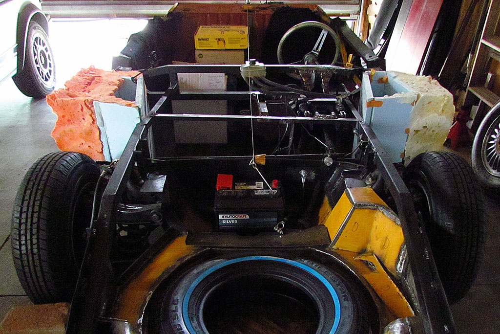
As a consequence, there was chemical corrosion under the battery on the battery well.
As I review the model, I feel the pressure to move faster and try to get this project done in two years.
I decide that the time invested correcting my contour guides and the model would be better spent sculpting the full-size body.
So I make the decision. As soon as my lease is renewed, I will begin the full-size body in August.
In the meantime, I will prepare the chassis to be covered by finishing some details.
The next big items are the gastanks.
One is partly built up.
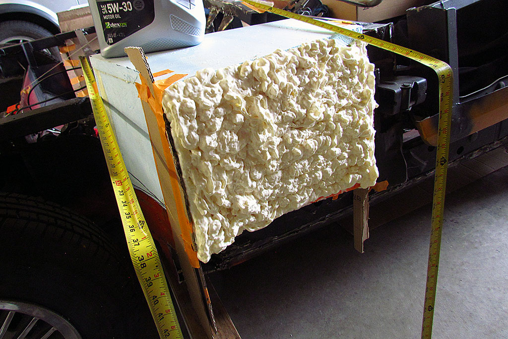
My plan is to use blue foam to make the rectangular core, and then spray insulation foam to make the shape that fits inside the curved fender.
I dig out my fender forms made in 2018 (see JUNE-JULY 2018.), and spayment on the inside clear plastic sheeting, and set it all up in position.
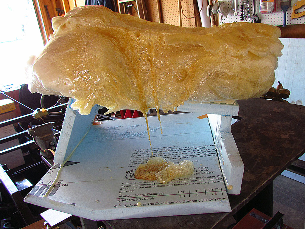
Then I inhale deeply and begin spraying the insulation foam into the fender cavity.
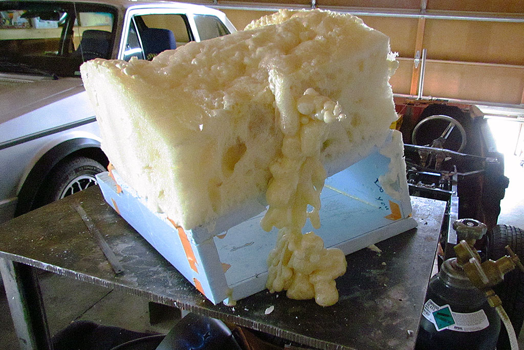
Turns out you can spray too much on at once.
It will sit and sit and then ooze down or drop onto the floor.
Also, it is best to spray a small line of foam rather than a big thick one.
It blends easier. It all has to set in an hour or two before doing more.
Another problem with spraying too much at once or too fast is that it WON'T set where the air can't get to it!
That makes for a real mess when taking it apart. It does require exposure to air to set!
Looking back, I would say I needed less of the blue foam core.
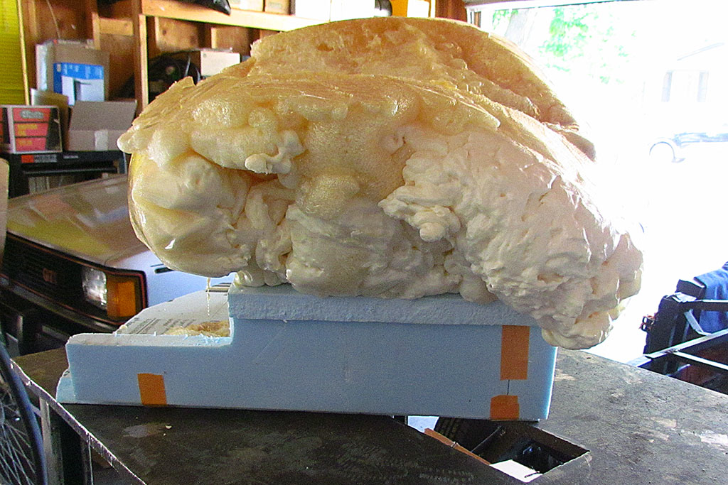
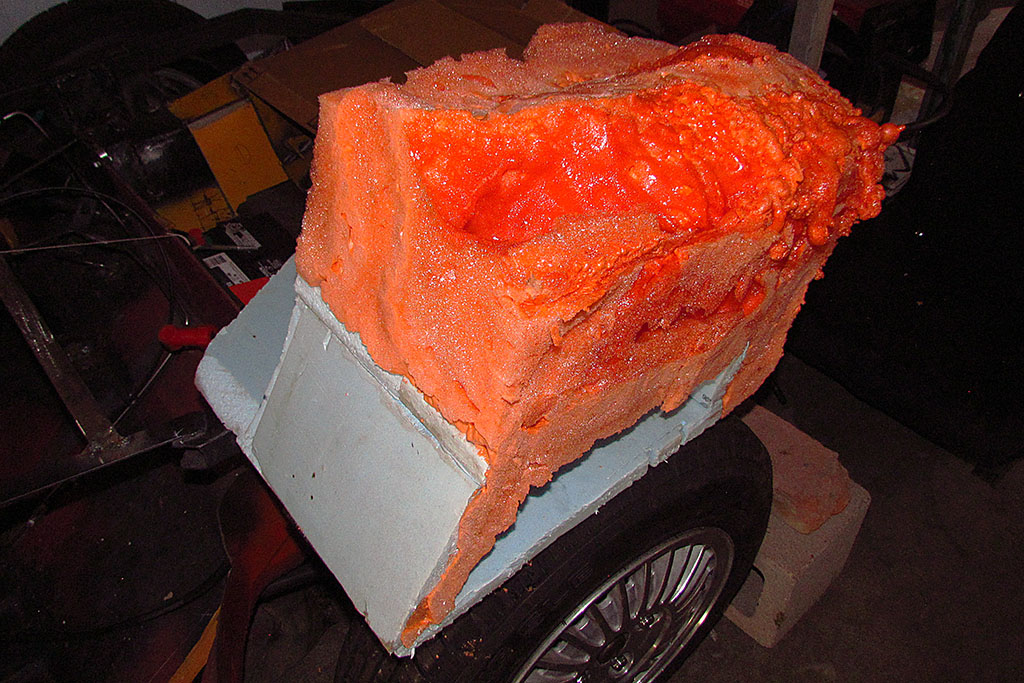
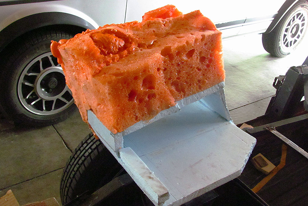
I used orange fireblock foam and regular gap-filling foam.
Both work. Once it sets, I think I prefer the fireblock foam to work with.
The regular works okay except where there is discontinuity where new layers of it meet.
Also, both require "touchup" with small squirts afterwards to fill large air pockets.
It took about 3 cans for each tank.
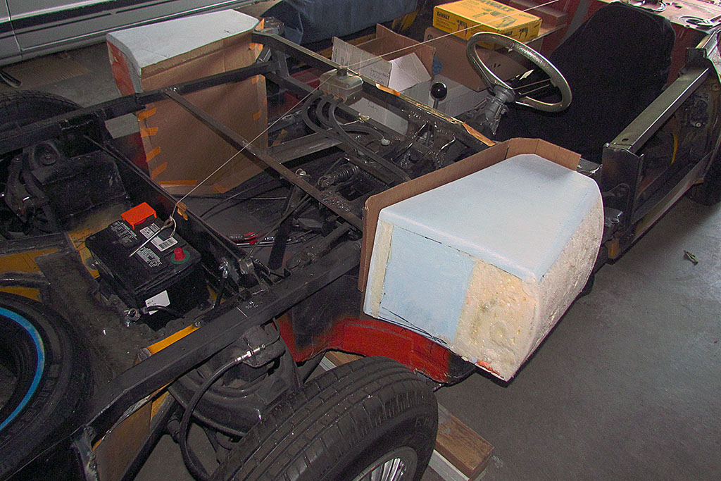
Next step is to carve it.
I used a hand-held hacksaw blade for rough cutting the shape, and a cheese-grater-like small hand rasp to do final shapping.
One can also use an 80 grit sandpaper and block. Oh - and a shopvac to clean it all up with!
I then fitted them to the chassis, and added blue foam or spray foam as needed.
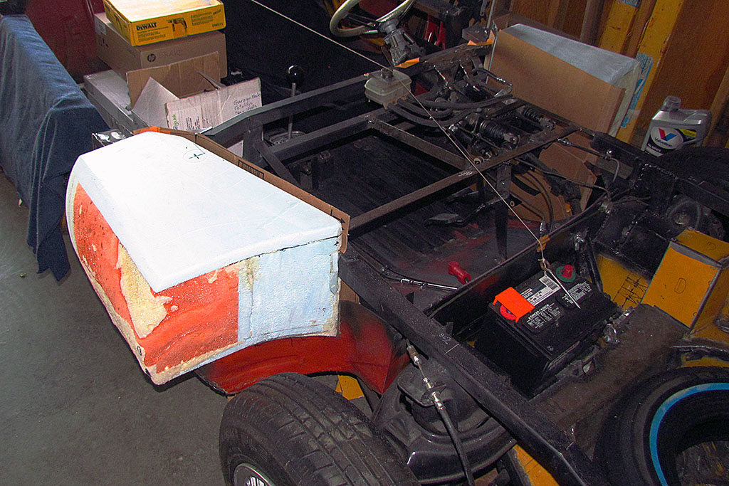
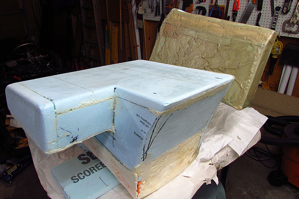
Once they are shaped comes the Aves paste covering.
Because it is sooo gooey and sticky, all you can really do is take a blob and spread it onto the foam.
I run the edge of my paddle across it to spread it more evenly, but the BIGGEST TRICK is to do ONLY the top (horizontal) surface at a time.
Then after it sets overnight, turn the tank and do the next surface. Repeat untill all surfaces are done.
This is done to let gravity even out the spreading of the paste.
If it is applied to a vertical surface, IT WILL RUN AND MAKE A BIG DRIP that dries that way!
Believe me - let gravity do its work for you!
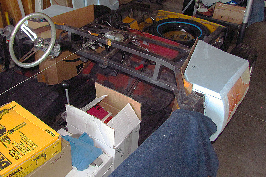
While waiting for the applications to set, I addressed some issues on the chassis.
First, I trimmed and cleaned up the crossover pipe where it comes to the gas tanks.
I realized I did not need to weld a corner pipe fitting.
I will instead run a 5/8" rubber fuel line thru the crossover and connect each end to a tube in the bottom of each tank.
Why did I not think of that sooner?!?!
I also need to prep where the engine-heated air comes out of the box frame member.
I cut open the end of the frame behind the front tire and pull out as much heater pipe as possible.
Remember that it had been cut in half when the frame was shortened, so it was no longer needed in the box frame.
I also added a lock nut to the safety brake wires.
PROBLEMS
During midwinter and again in early spring, there was this odd, egglike odor in the garage for a couple of weeks at a time.
I could find nothing dead and so just wrote it off to Front Range farm smell blown in from the east, which happens from time to time.
But one day in early summer while walking past the chassis, I noticed one of the battery caps was off and missing out of the corner of my eye.
That was odd. So I looked for the cap and found it 5 feet away! Very odd! And looking into the battery saw dry cell plates. Very serious!!
I added water - an entire gallon - and then realized what I smelled in the winter.
What happened was overzealousness on my part. I had left the battery charger connected to the battery for weeks rather than get a trickle charger.
I boiled the battery juice all out and ruined the battery.
It also did some mild corrosion to the battery plate and the sheet metal underneath, as shown in the photo.
New lesson learned... the usual way.
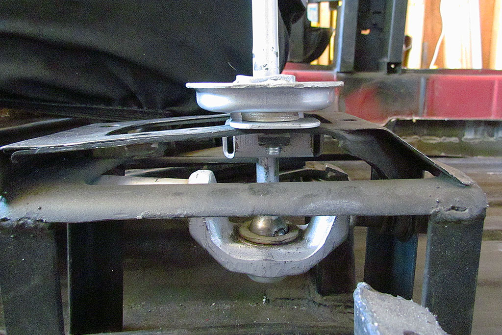
More constructively (pun unintended), I also attempted to get the gear shift to go into all gears.
Where I last left it, it could only go into reverse, 2nd, and 4th.
I raised the shifter assembly slightly up by two washers, and moved it forward about 1/4".
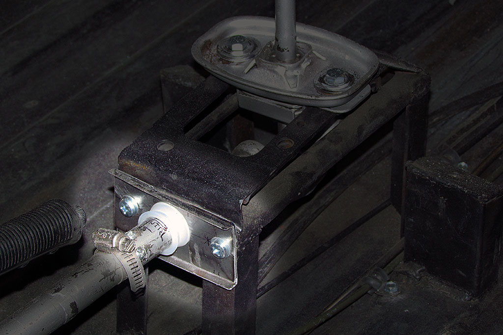
That helped, but I also decided to make a shift rod guide near the gear shifter so it would not oscillate as the shifter rotated left and right.
Not sure that helped reach 1st and 3rd much, but it is not wiggly anymore.
SEPTEMBER
I begin getting ready to make the body.
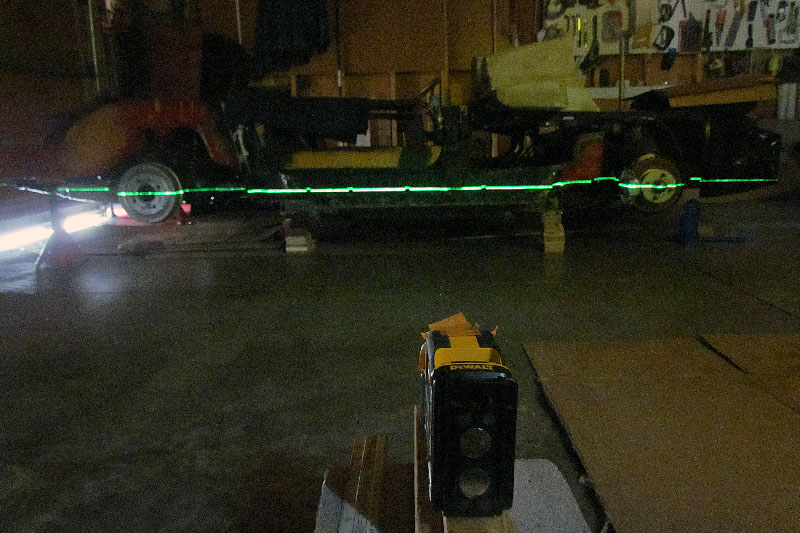
First order of business is to level the chassis for measurments.
Using my laser level, I get the front and rear axle centers aligned horizontally, first left side, then right side.
Checking it back and forth from left to right, I go thru the exercise three times.
I was able to most accurately measure the wheel base, which becomes my datum line to measure from, and then make other measurements such as the location of the floor pan.
I also do some grinding and cutting cleanup.
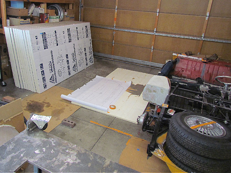
I then calculated how much foam I expected to use, and brought home a dozen isocyanurate insulation panels.
SIDEBAR: How to Make a Fiberglass Body
How was I going to make the body?
I was not going to learn how to pound sheetmetal, so for sure, it was going to be made of fiberglass.
There are three ways I have seen to do so: plaster, clay, or foam.
Plaster was popular with early fiberglassers in the 50s.
It involved typically cutting out contours as one would to form sheetmetal, but then covering them in wire mesh and coating it with plaster.
One then sands it down to shape and adds more where needed and sands again, repeating as needed until done.
Plaster dust is messy and the body weighs hundreds of pounds, but it is rigid and smooth.
Clay has been used by the auto companies since the 30s unto the present day.
Originally a wooden buck was made and clay a couple inches deep was spread over it.
The clay was a special formulation made with a high content of wax.
It was relatively easy to sculpt and could be changed easily.
When smoothed, it could be cast with a good finish.
It, too, is heavy, but is reusable and holds fine detail, and can accpet changes readily, but it is not cheap.
Foam is a newcomer to the process.
It is used by the auto companies as the core under the clay nowadays.
It can be used as the basis for the body and save hundreds of pounds of weight.
The isocyanurate type of foam resists chemicals and heat unlike most other foams.
It is not as accurate to work with as plaster or clay, but can accept Bondo or other body putties to build up a final crisp and accurate surface for molding.
There are variations mixing the three materials.
I decided on the foam approach for its lightweight property.
To harden the foam surface, I intend to follow the technique used by Mel Francis of covering it in a layer of fiberglass and then coating it in Bondo to get the final surface.
Then a fiberglass mold is made of the hard-surfaced foam, and the parts are made from the molds.
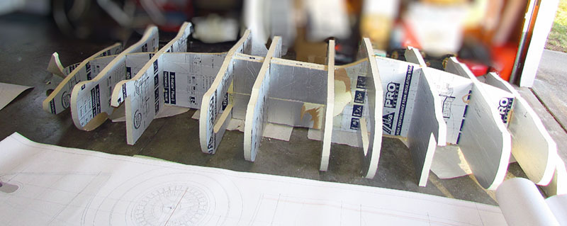
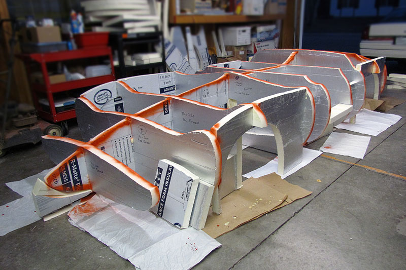
OCTOBER - NOVEMBER
I thought I could cut out and assemble the cross-section skeleton frame in a week in Sept.
I could not. It took, between work and the rest of life, all month of October.
But now I was looking at the real size of the vehicle, instead of imagining it on the chassis.
I seemed longer and narrower than expected, but it kept measuring correctly.
A visual illustion.
While I was at it, I also added pieces to represent the center console.
I also had to add pieces to reinforce where the two halves of the lengthwise center contour met.
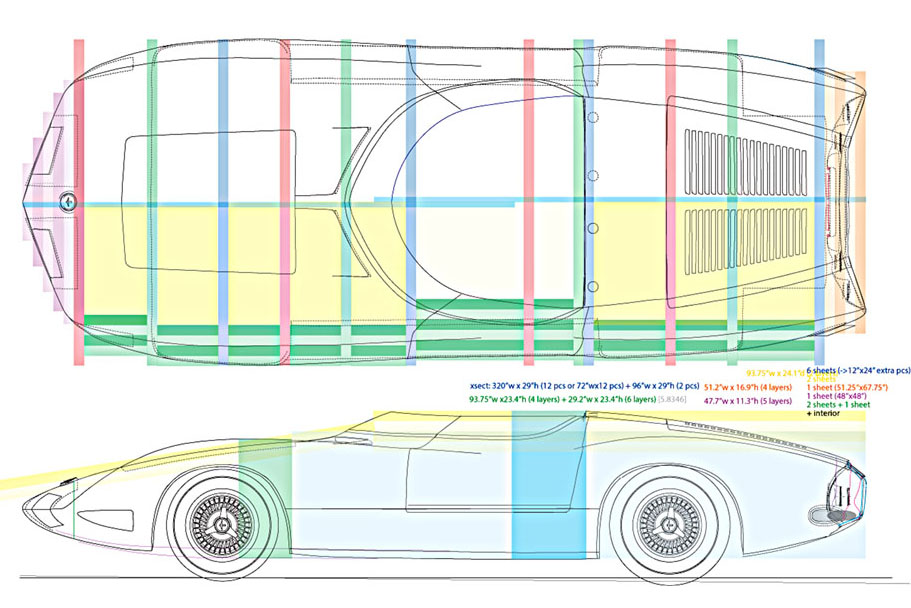
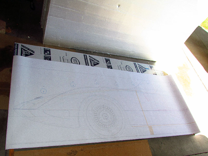
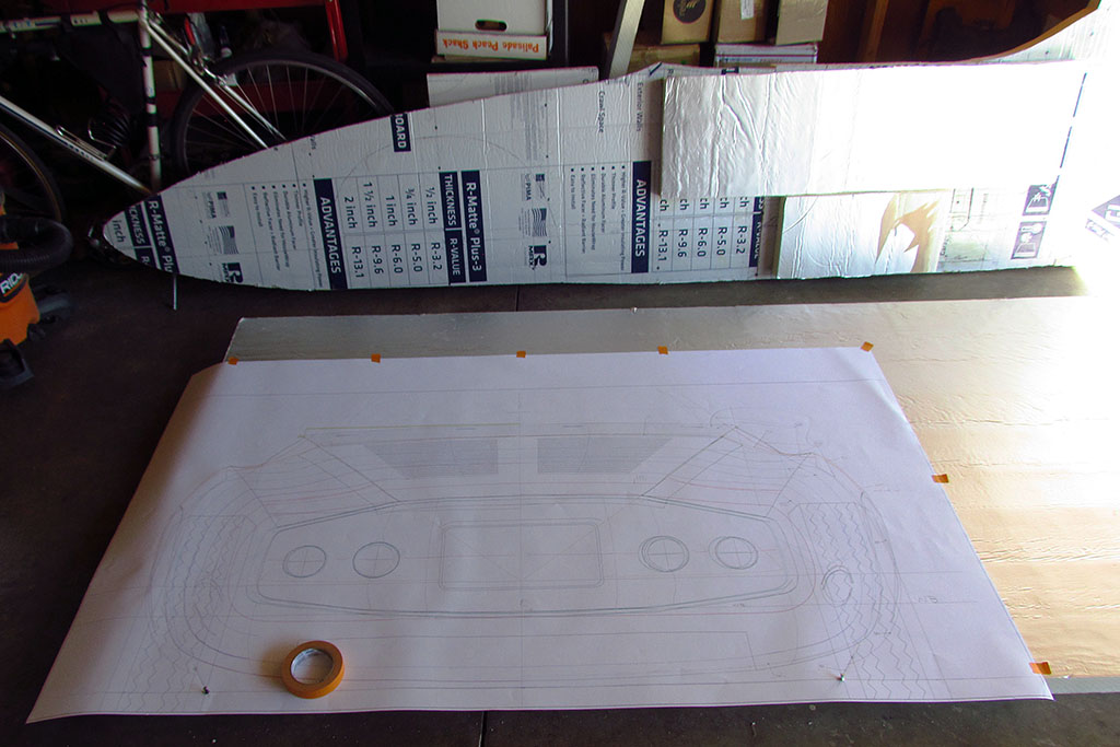
The technique is simple. I outputted my elevation views full size on a Kinko plotter.
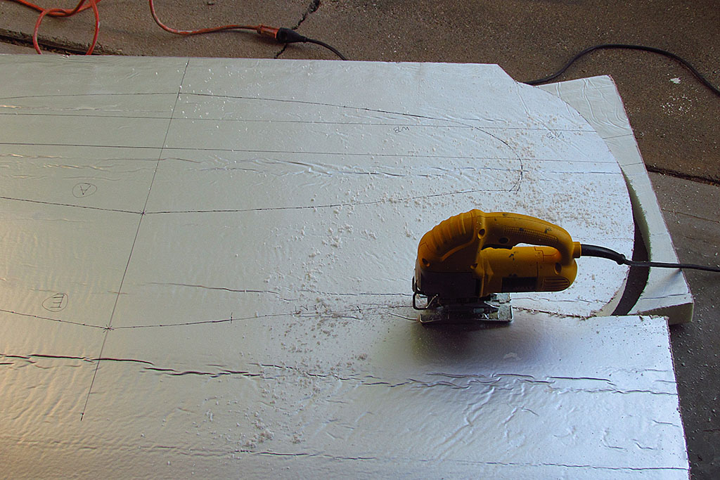
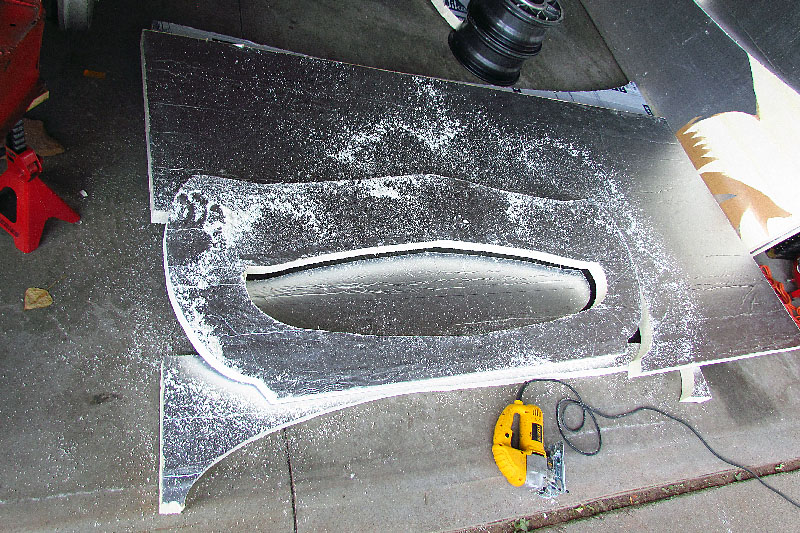
I then tack-traced the contours that I plotted out earlier onto the foam panel, then hand-inked the contour line and cut it out.
I first tried to use a hacksaw blade by hand, but I could not control how vertically I held it, which created a slanded cut.
I switched to a saber saw that would go thru the foam like warm butter.
Next, the contours were notched to lockfit into each other and then glued.
I used Gorilla glue on the skeletal contours.
I kept the foil and plastic film coatings on the contours to mark there the edges where for later when I sanded down to them.
I also painted them red to help them stand out.
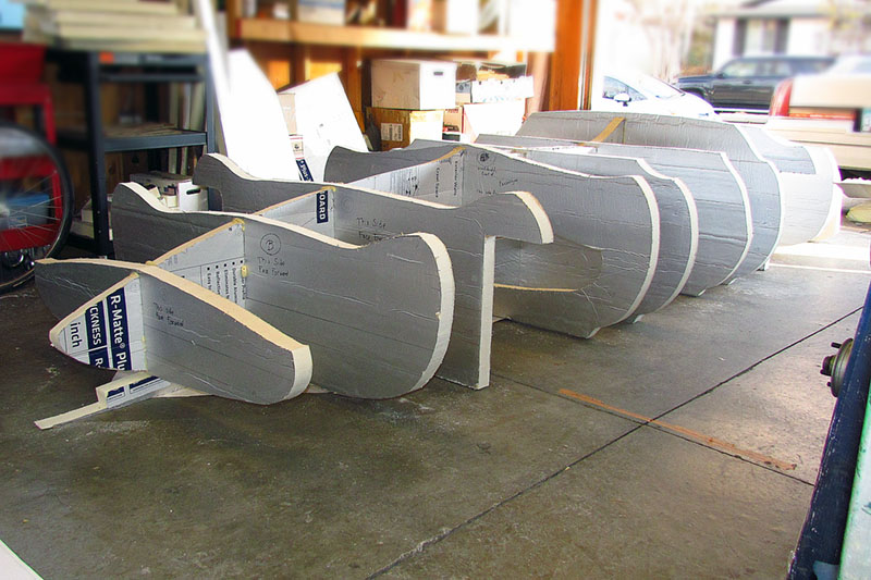
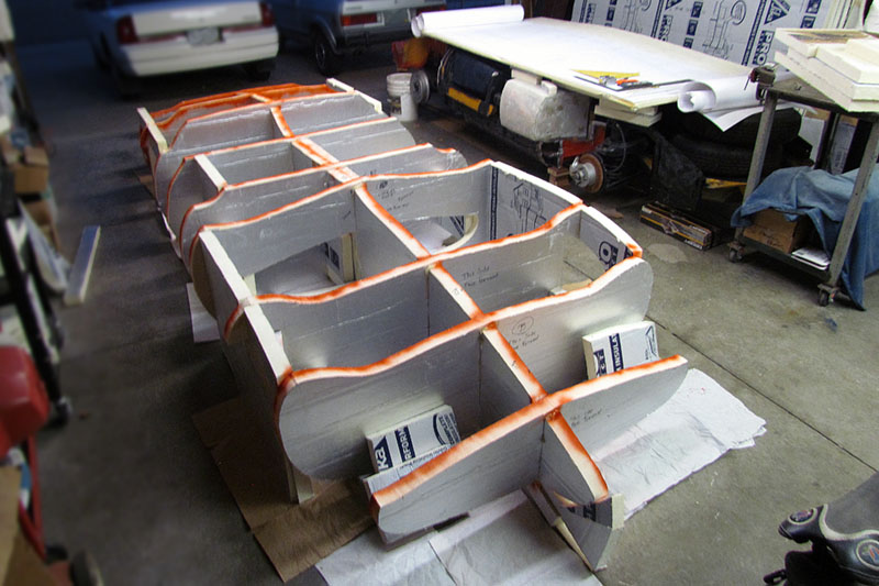
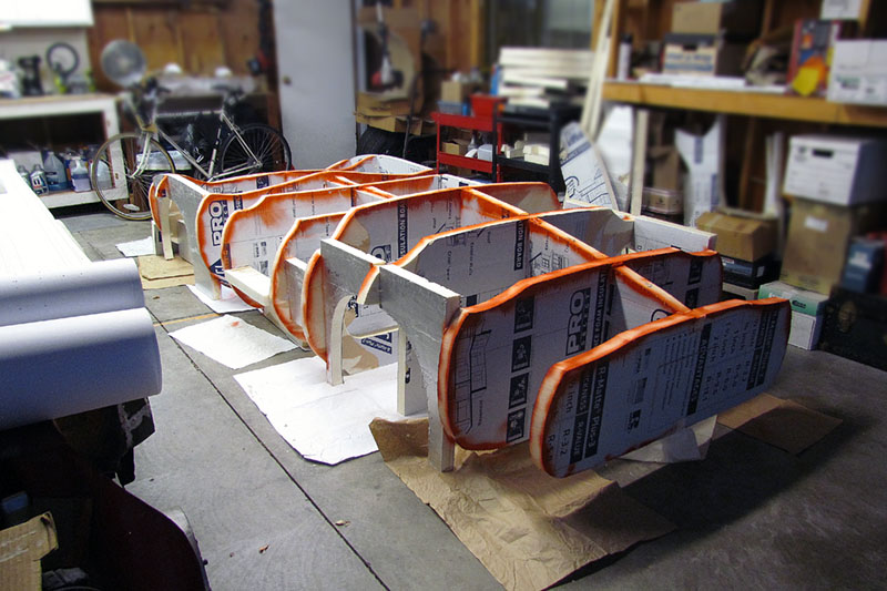
Next up - start adding in the filler panels.
I quickly added some spacers to maintain the correct spacing along the frames.
I tried at first to angle largerer panel pieces from one frame to the next.
That turned out too tricky to get a good fit, so I reverted back to using multiple layers.
That had the advantage of right-angle fit and more thickness for sturdiness and more surface area to glue.
The disadvantage is added weight later when moving it.
The Gorilla glue did not work so well for the panels. It did not hold well.
That stopped me for a couple weeks while I figured out something else.
Contact-cementing panels to each did not work either.
It was not strong enough to hold them together when there was a slight bow to a panel.
I settled on Elmers White Glue, all-purpose, liberally coating an entire surface.
Since temps were now down to the teens to thirties in the garage and I am limited to 120V heaters, and those heaters can't make a dent in the cold, I glued the panels together in a spare room in the house.
The panels were also weighted down to counter the panel bow and make a good seal that did not separate while drying.
Then I fit the panels, something working them to fit, and fiddling with my clamps and boards to press things together to dry overnight in the 30-minus temps.
More white glue was added around the seams and joinery.
It worked, happily, I think.
The next step when the rear section is panelled together is to shape it and see how well it holds up!
Check out 2022 for more progress!
SIDEBAR: How to Make a Fiberglass Body
How was I going to make the body? I was not going to learn how to pound sheetmetal, so for sure, it was going to be made of fiberglass. There are three ways I have seen to do so: plaster, clay, or foam.Plaster was popular with early fiberglassers in the 50s. It involved typically cutting out contours as one would to form sheetmetal, but then covering them in wire mesh and coating it with plaster. One then sands it down to shape and adds more where needed and sands again, repeating as needed until done. Plaster dust is messy and the body weighs hundreds of pounds, but it is rigid and smooth.
Clay has been used by the auto companies since the 30s unto the present day. Originally a wooden buck was made and clay a couple inches deep was spread over it. The clay was a special formulation made with a high content of wax. It was relatively easy to sculpt and could be changed easily. When smoothed, it could be cast with a good finish. It, too, is heavy, but is reusable and holds fine detail, and can accpet changes readily, but it is not cheap.
Foam is a newcomer to the process. It is used by the auto companies as the core under the clay nowadays. It can be used as the basis for the body and save hundreds of pounds of weight. The isocyanurate type of foam resists chemicals and heat unlike most other foams. It is not as accurate to work with as plaster or clay, but can accept Bondo or other body putties to build up a final crisp and accurate surface for molding.
There are variations mixing the three materials. I decided on the foam approach for its lightweight property. To harden the foam surface, I intend to follow the technique used by Mel Francis of covering it in a layer of fiberglass and then coating it in Bondo to get the final surface. Then a fiberglass mold is made of the hard-surfaced foam, and the parts are made from the molds.
The Build--2021
January
(L) The pedal frame in stereo, parallel view method.
(C) The new accellerator cable attached to the the accellerator and pedal frame.
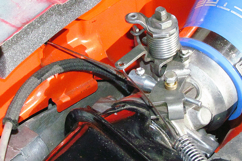
(R) The throttle body with the new cable attached.
March
Problems
1st ROW
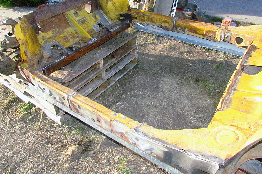
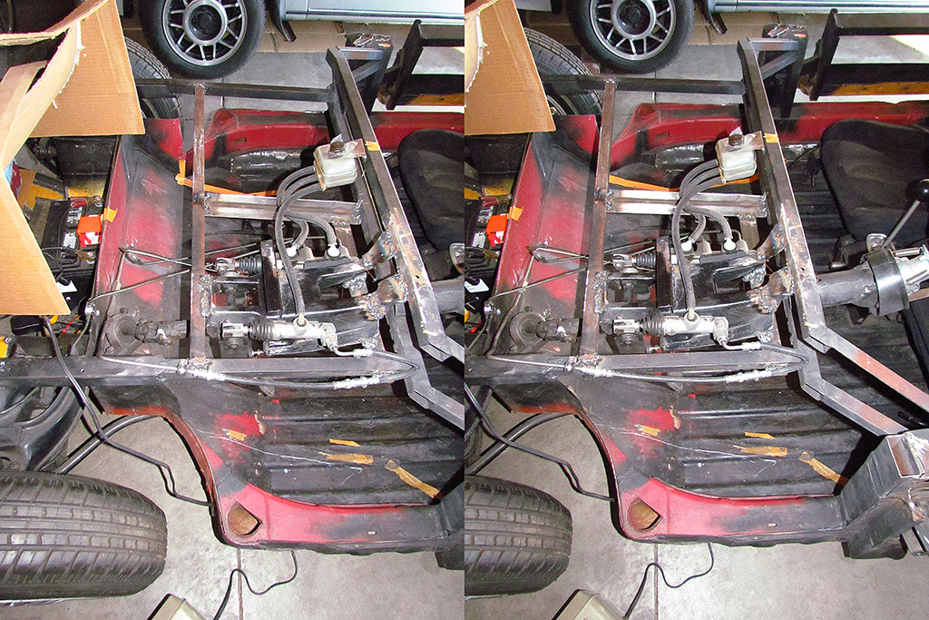
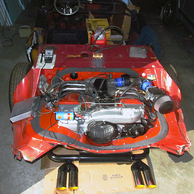
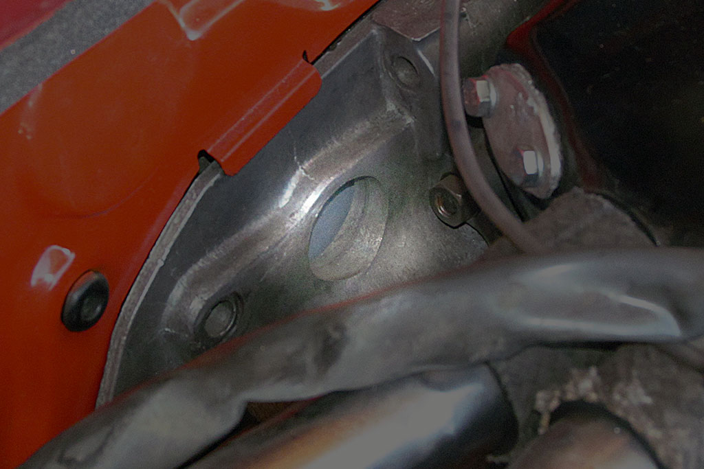
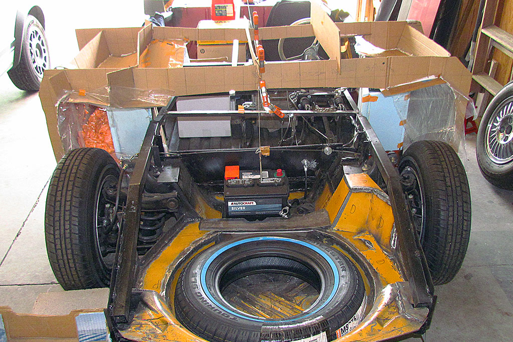
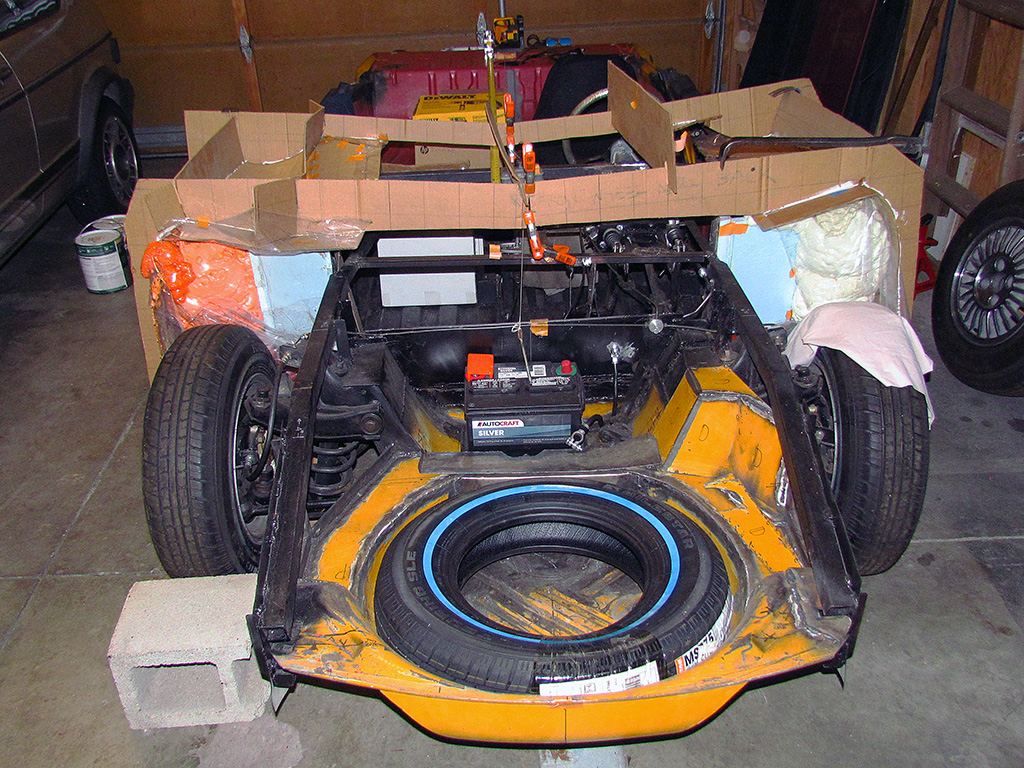
(L) Engine compartment viewed from behind
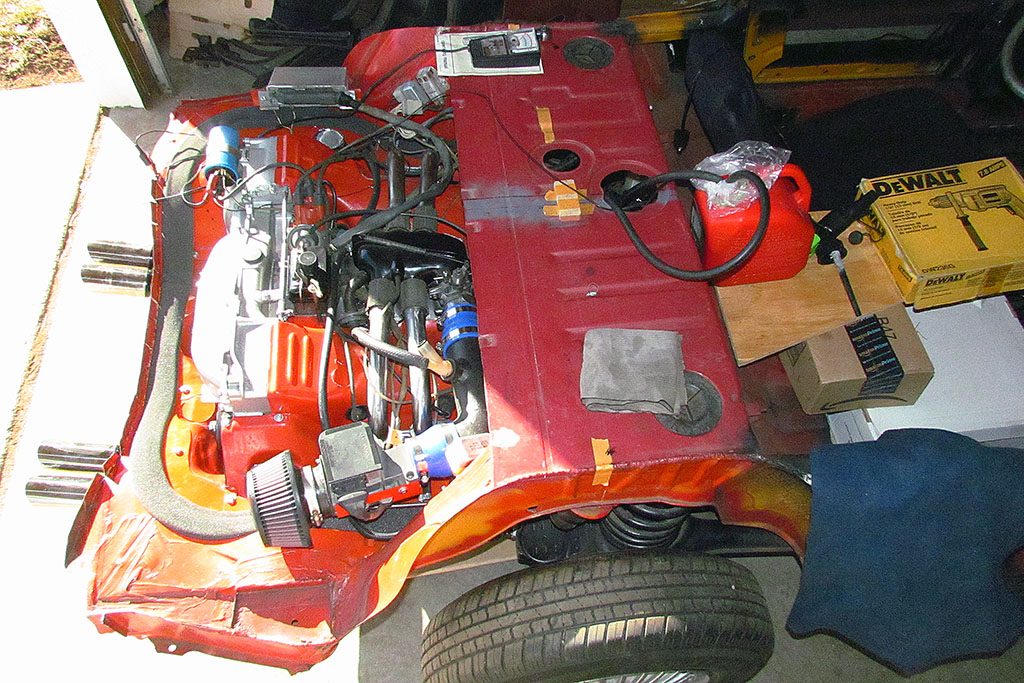
(C) Engine compartment viewed from side
(R) (movie) Starting up the engine... and the smoke.
2nd ROW
(L) An open hole into the clutch housing. At first I thought the smoke was coming from here.
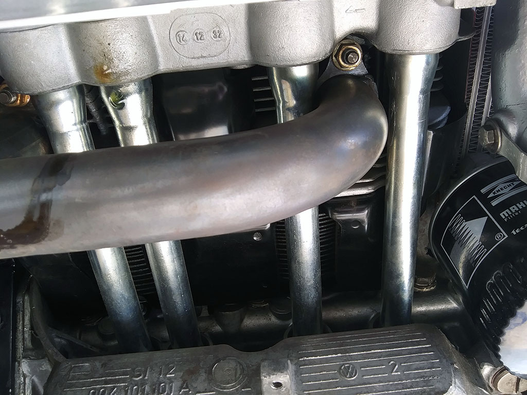
(C) An underside view of the push rod sleeves. The oil forming on the end of one sleeve marks the culprit.
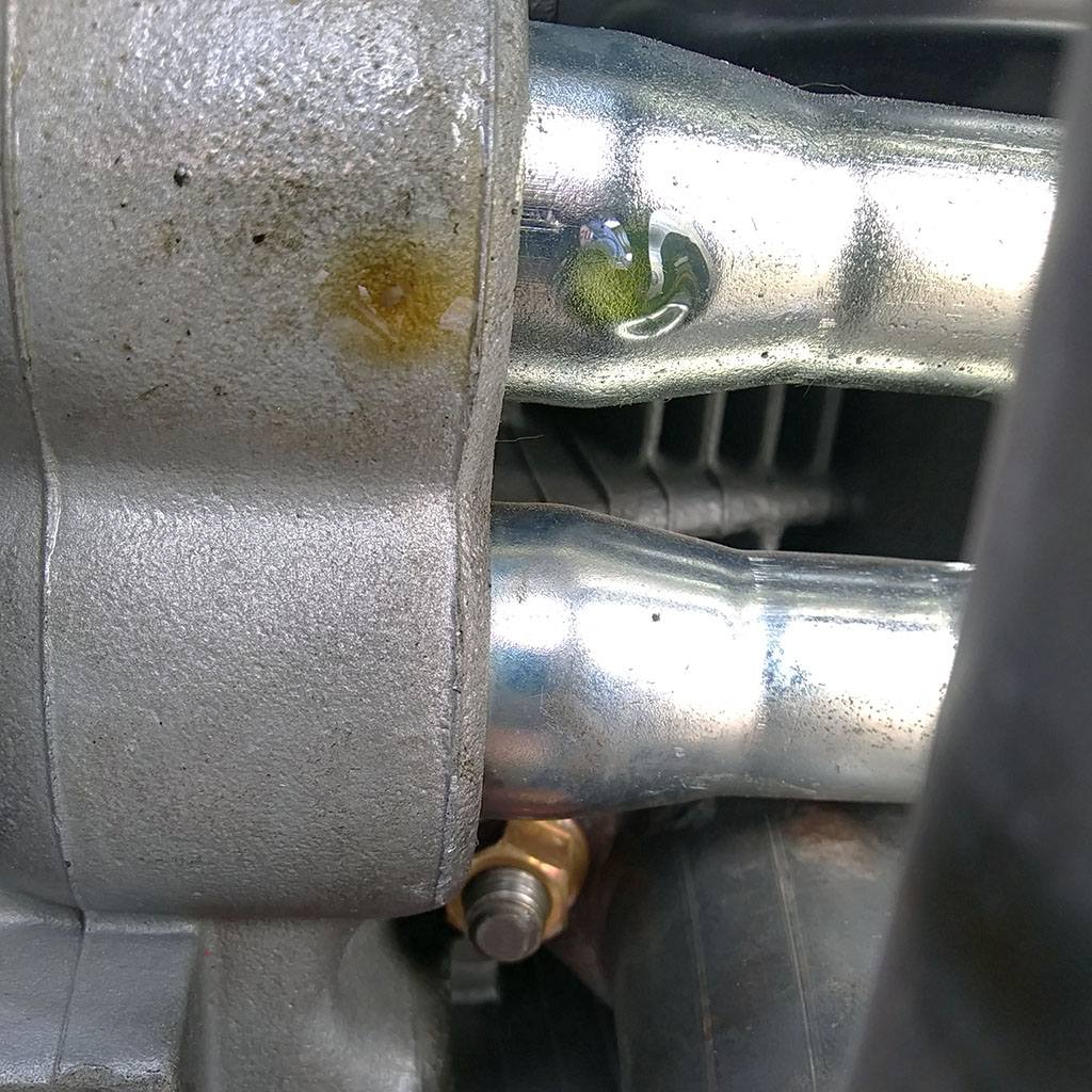
(R) Closeup of the leaking push rod sleeve.
February-May: The Model
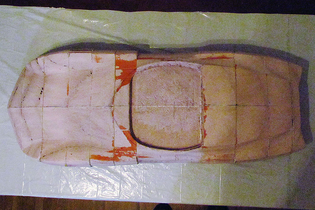
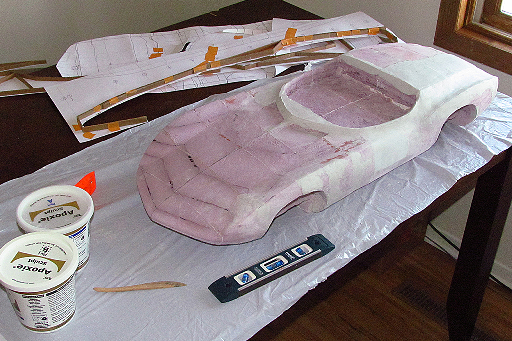
1st ROW
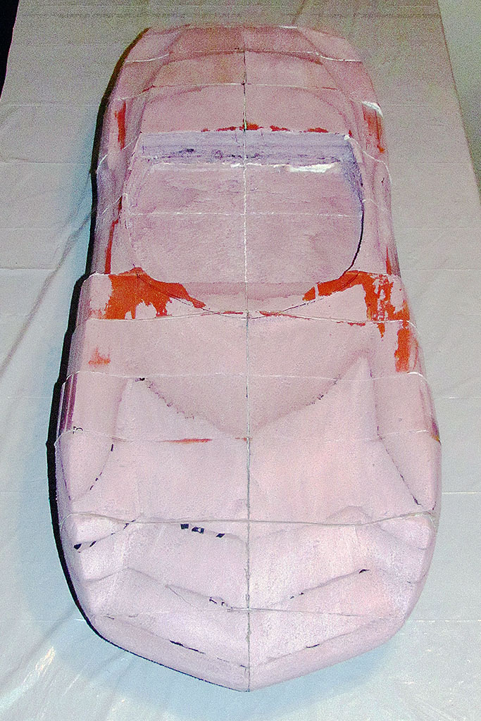
After the first overall sanding:
(L) Front view. The orange-red color is the remnant of a latex paint test to seal the surface.
(C) Top view
(R) Rear view
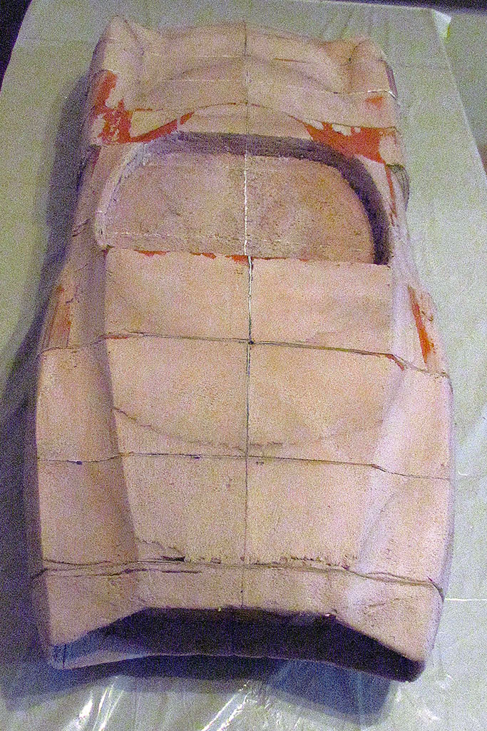
2nd ROW
First application of Aves putty:
(L) Driver side. I soon decided to do one side first and work out the shapes there, then do the other side.
(C) Top view
(R) Rear view
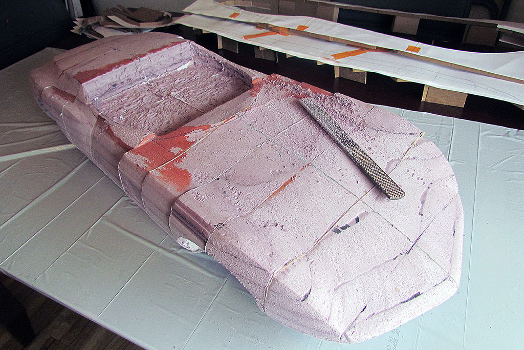
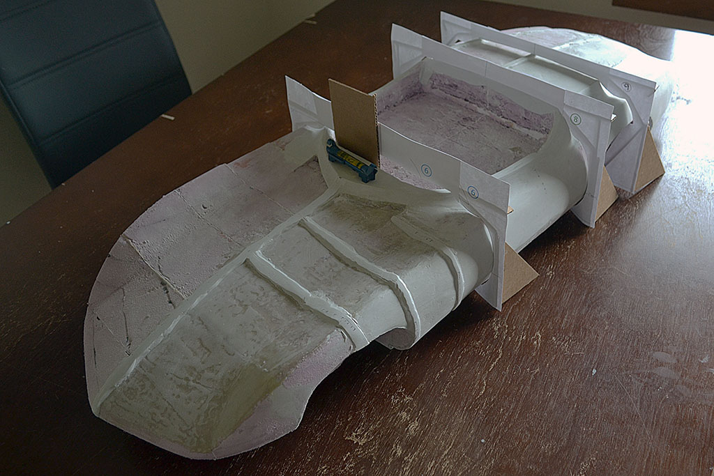
3rd ROW
(L) Out of sequence. I used this hand rasp/file to shape the foam to the contours.
(C) A template to check the engine hood and rear fender ridge locations.
(R) Working with the half contours
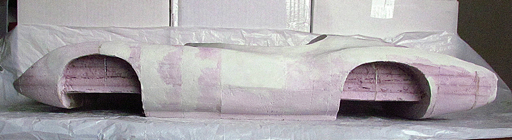
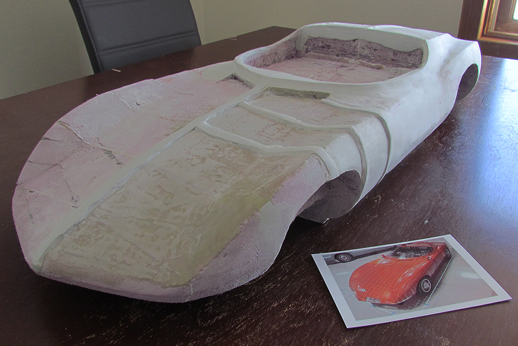
4th ROW
(L) Front-on view
(C) Matching the view in the color photo
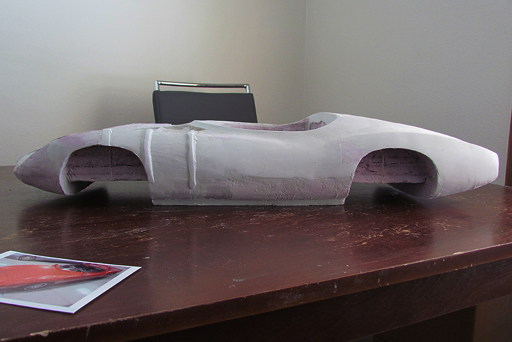
(R) Side view. I decided to establish the ridges and the contours first and then work the rest of the body to them.
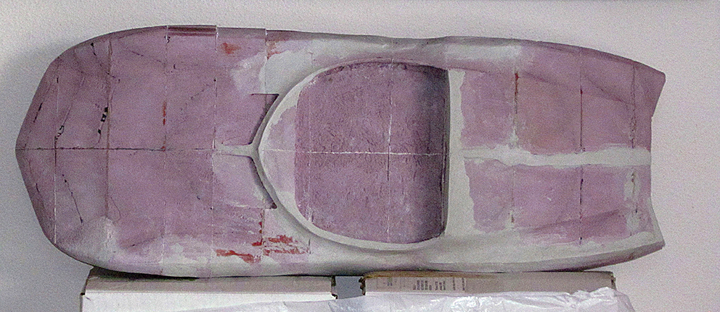
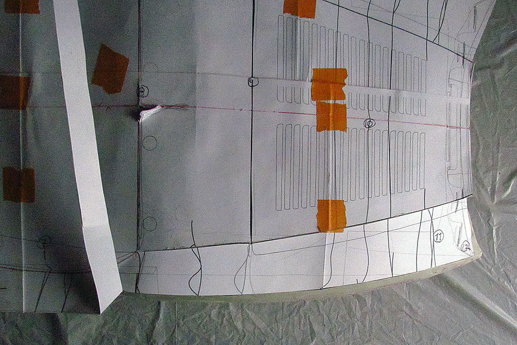
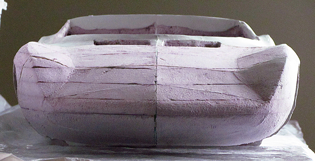
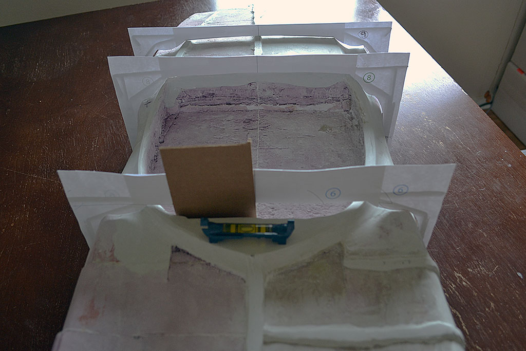
5th ROW
(L) Creating a new set of full-width contours.
(C) A backlit, head-on view shows where the contours need brought up.
(R) I think I found my paint job. A very candy color-like film wrap will do very well at 1/6 the price!
June
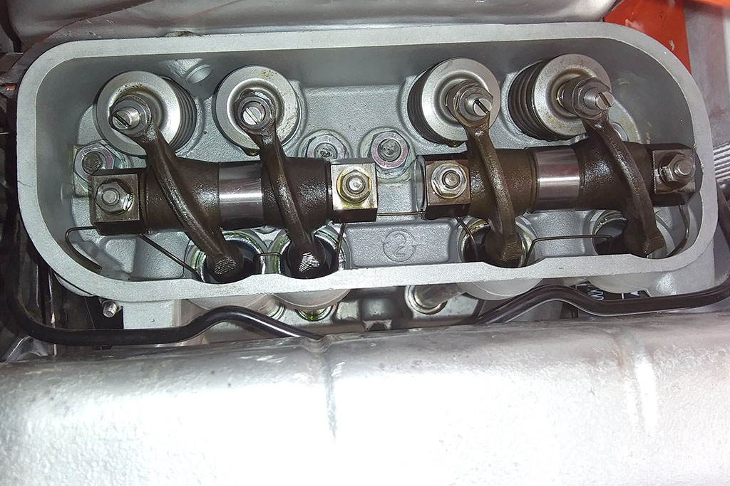
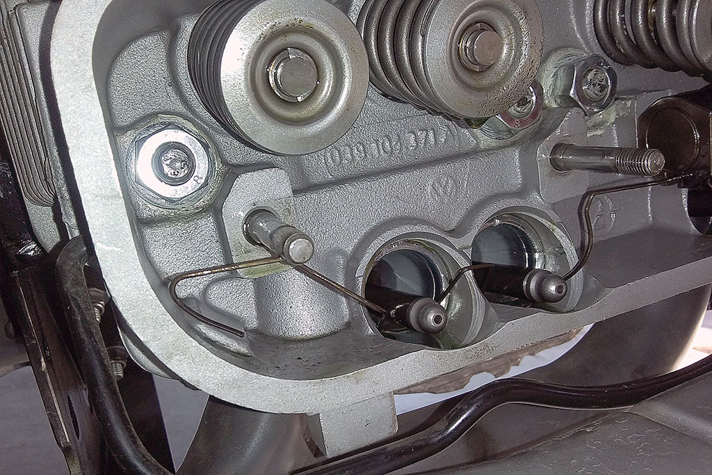
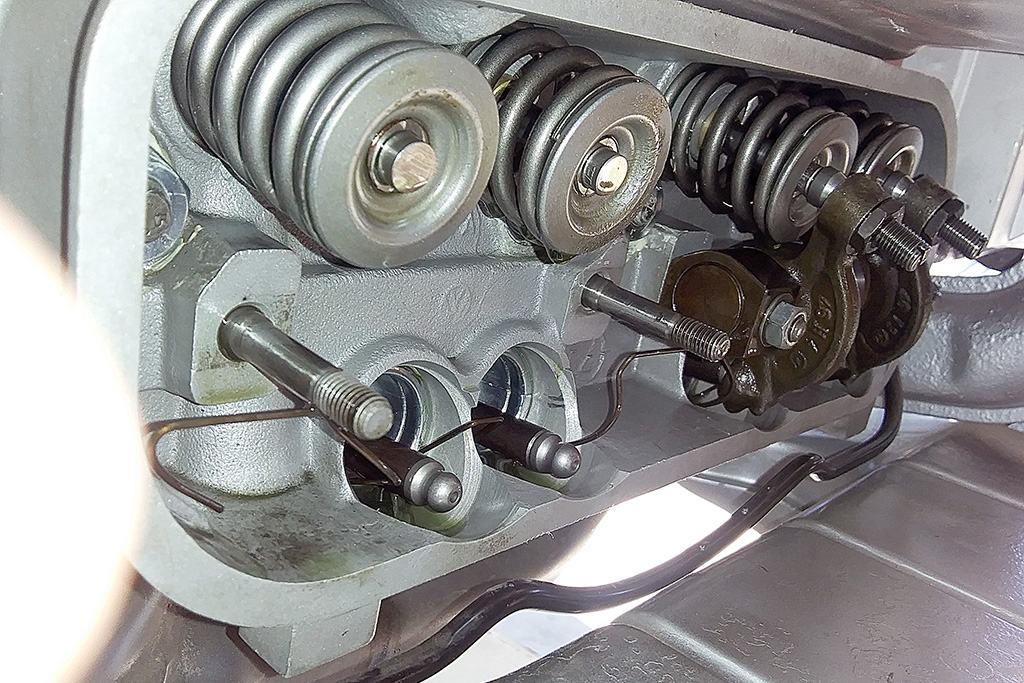
(L) The inside of the cylinder head, showing the rocker arms. The rocker arm came off easily.
(C) Closeup of the push rods with one of the rocker arms removed. Note the wire around the push rods.
(R) A wider view better showing how the wire around the push rods bends.
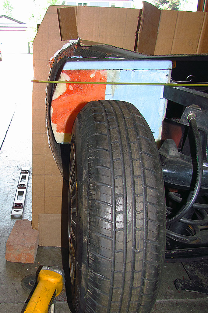
June-July
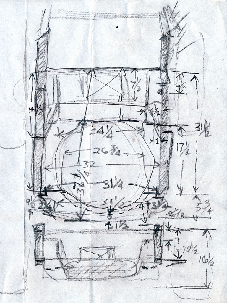
1st ROW
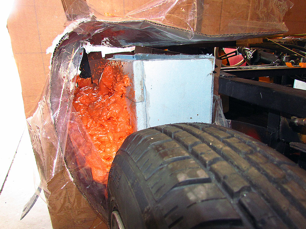
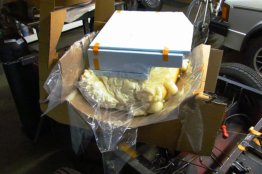
(L) The initial setup using the fender forms and blue foam cores.
Note the first application of fireblock foam on the passenger side.
(LC) A closeup of the fireblock foam first squirt. Ugh! What a mess!
Note the clear plastic covering the cardboard fender form.
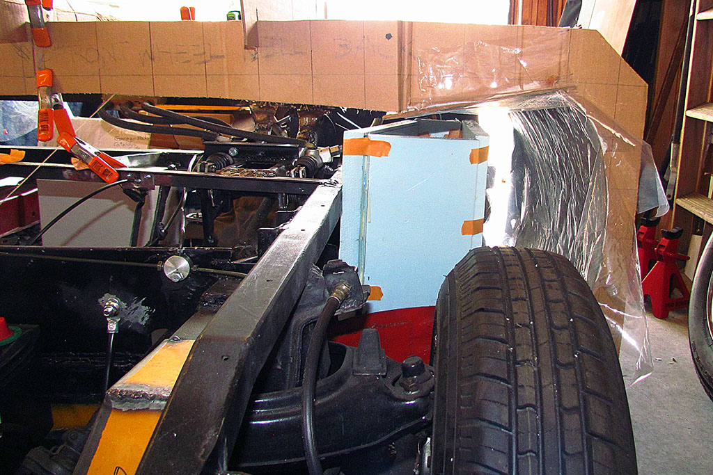
(RC) Here's the driver's side before spraying insulation foam into it.
(R) My notes of measured dimensions of the front chassis framing.
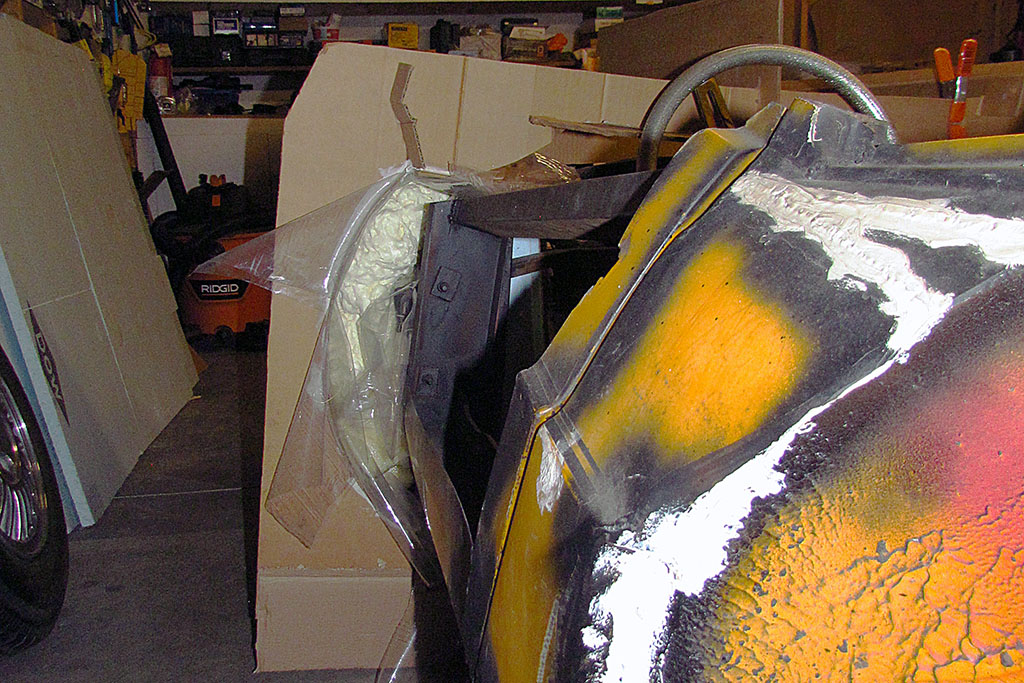
2nd ROW
(L) The view of the driver side tank+foam in the form from behind.
(C) Here's the 2nd squirt on the driver's side. All filled in . . . so I thought.
(R) And the passenger side from behind, all filled it . . . more or less.
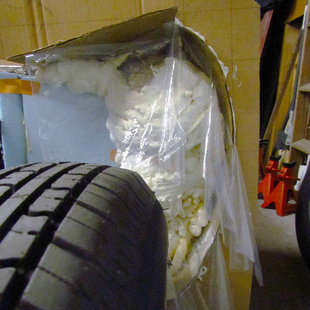
3rd ROW
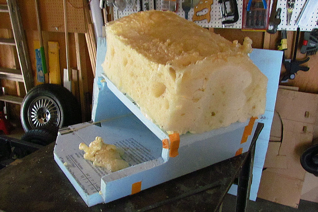
(L) Thinking I had succeeded, here are both tanks, ready to pull out and remove from the form.
(C) The driver's side tank+foam in the form.
I used regular gap-filler foam on this side.
The dark yellow around the edges on the right side of the foam is where is did not cure well and had pooled as a gooey liquid.
(R) And the passenger side tank and form. Same curing problem.
Note that the cardboard partition came out with the tank.
A metal partition will separate the tank from the passenger compartment on each side.
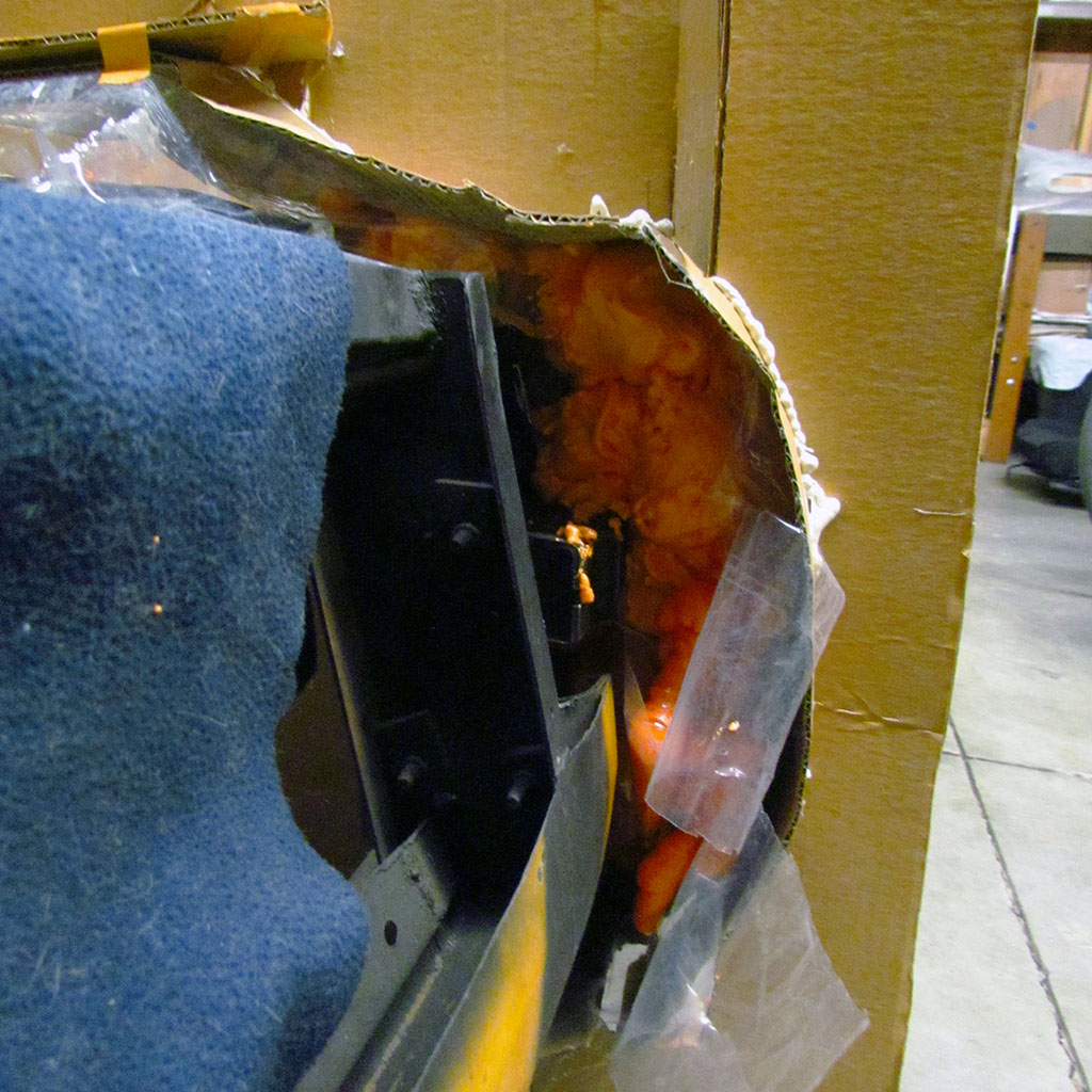
4th ROW
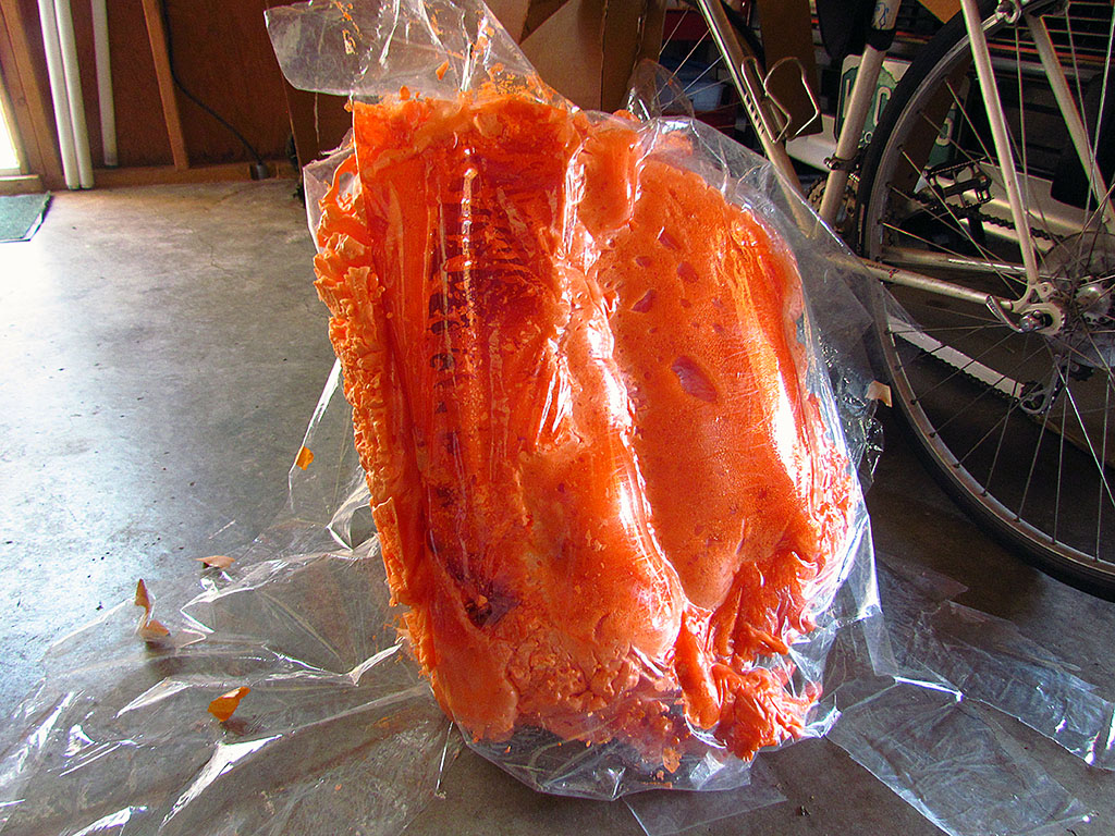
(L) Free from the form, I discovered big, gooey air spaces that were uncured.
I pulled off the plastic (stickiness on everything it touched) and let is air cure a couple days.
(C) Same problem on the passenger tank. This would require additional foam to build up.
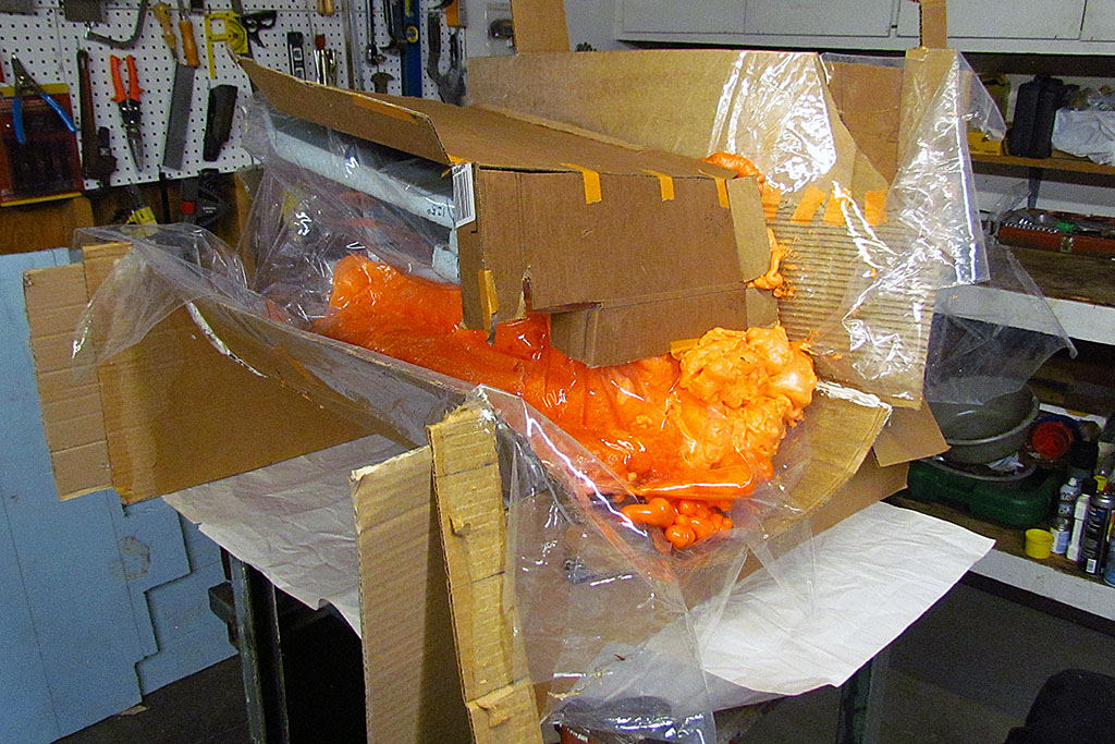
(R) This shows what I got by trying for fewer but bigger squirts.
The 3rd squirt would have to be done slower laying down a smaller bead of foam; sorta like welding a bead.
Shaping & Coating
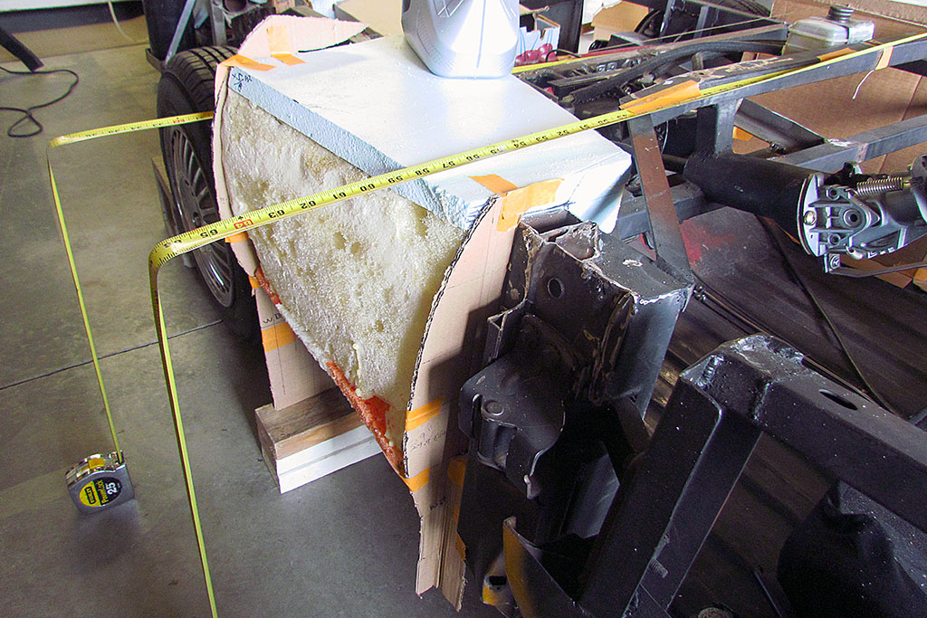
1st ROW
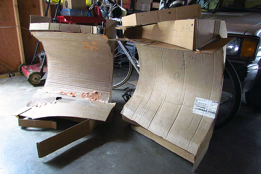
(L) The forms after removing the tank plugs.
(C) The passenger tank with the first trim cut.
WAY too much foam . Lotsa waste on both sides.
(R) The view of the underside of the tank.
2nd ROW
(L) The driver's side tank with first cuts.
(C) The post-removal aftermath of post-curing.
(R) Test-fitting of the tanks as I trim.
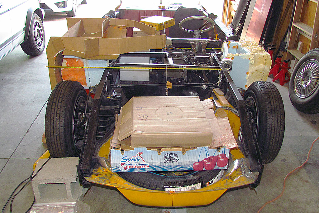
3rd ROW
(L) And checking for the centerline to measure body width at the tanks.
(C) Adding pieces to help gas drain down, and to maximize my tankage.
(R) Passenger side tank looks pretty good.
Note the new foam application on the driver side.
4th ROW
(L) More measuring and test fitting.
(C) Close enough is good enough. I am pretty sure my form is not exact.
(R) Passenger side tank as seen from the footwell.
I will need to add a metal box extension from the frame past the inside wheel well for the hot air for the ventilation fan.
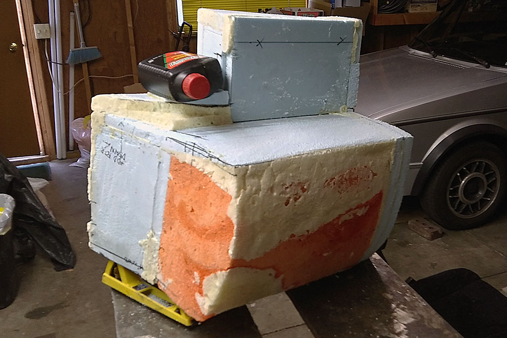
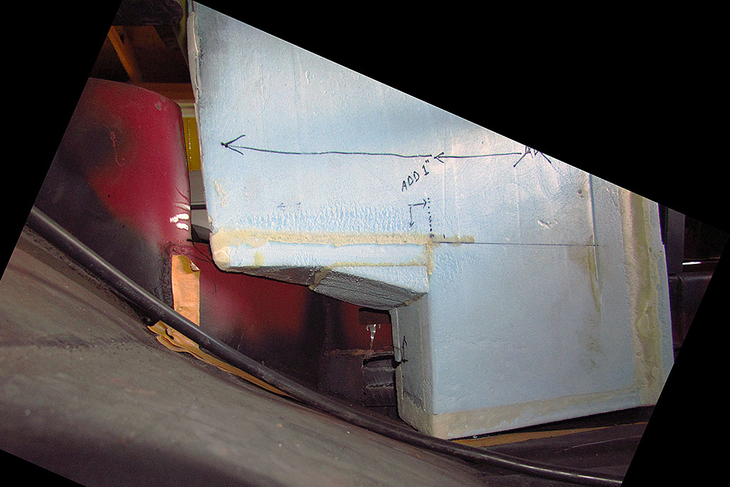
5th ROW
(L) Again measuring, this time for the driver's side tank.
I suspected the outside contour was off, but by how much? And how much foam would be needed?
(C) Well, about THIS much!
(R) A new squirt done in place, on the vertical, whith short squirt beads. That should do it.
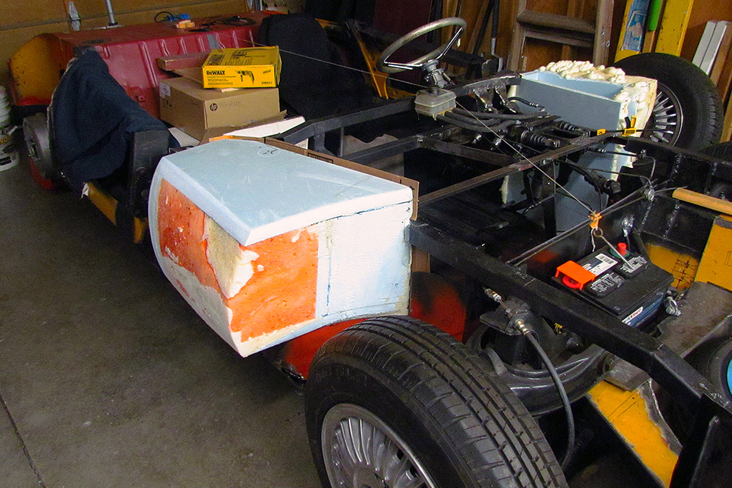
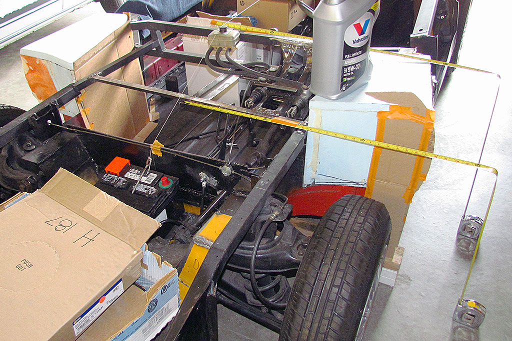
6th ROW
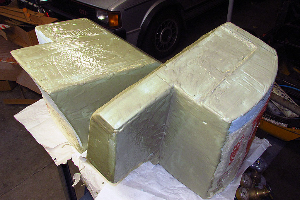
(L) The shaped driver's side tank in place.
(C) The view of both in place.
(R) The view of both from behind.
7th ROW
(L) Mixing a small batch of 2-part Aves Apoxie Paste
(C) Note the back tank where I applied the paste to a vertical surface (now turned on its side) and the drips created.
(R) One side at a time. Almost done. Two sides to go.
Problems
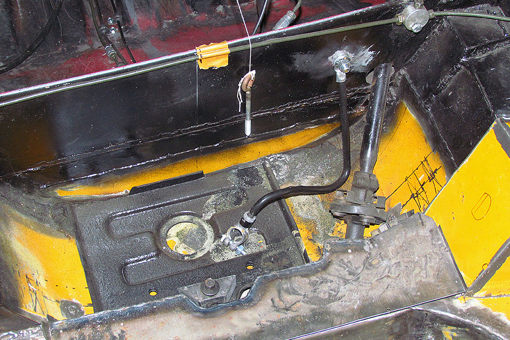
(L) Corrosion in the battery compartment.
(C) Side view of the shifter. Note the two washers for spacers.
(R) The new shift rod guide plate made of two pieces so I would not have to remove the shift rod.
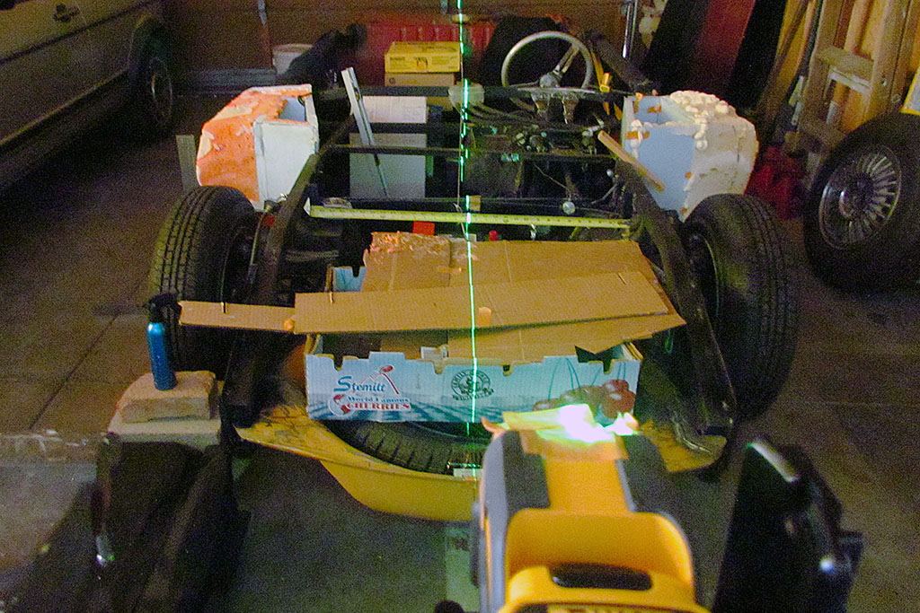
September
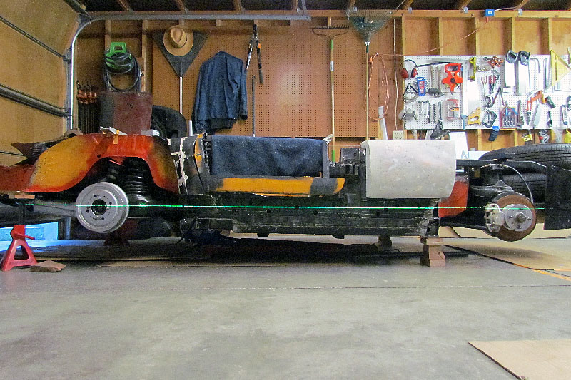
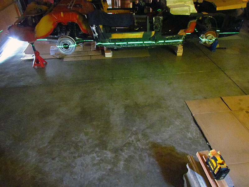
(L) First attempt. I aligned it to how the body sits. But then I realized that the car sits on tires of different diameters. It actually sits lower in front than the actual body was designed to.
(C) That means, I should really align it to the CENTERS of wheels!
(R) After a couple of back and forths from right side to left side, I get it leveled all around relative to gravity. The garage floor is not exactly level.
It is only then it strikes me the chassis is not sitting ON the wheels. The wheels are hanging down. But there is very little deflection, I have noticed, when they do sit on the wheels. I am just hoping it's neglible.
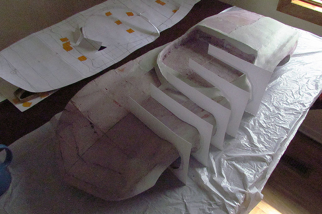
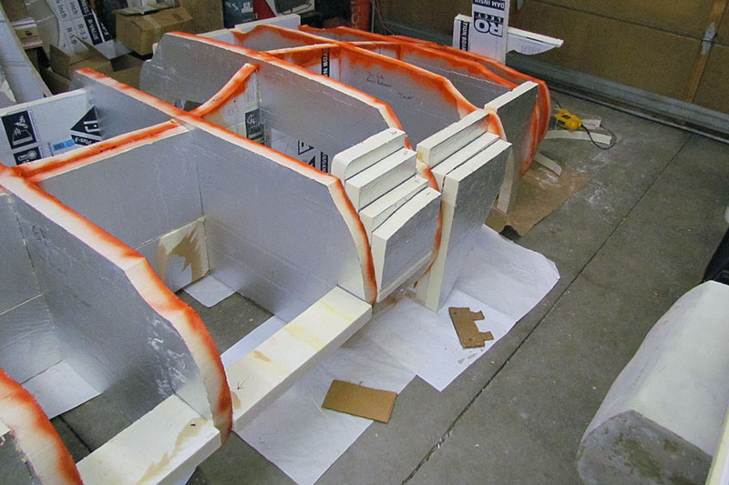
October-November
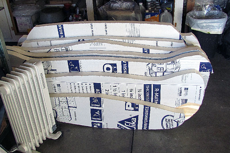

1st ROW
(L) My drawing calculating how many sheets of foam I expect to need. Eleven, with one to grow on.
Laying out the contour onto the foam (tack-tracing from the full-size drawing) and freehand inking the contour by connecting the tack marks.
2nd ROW
And then cutting it out with the sabersaw. And repeating.
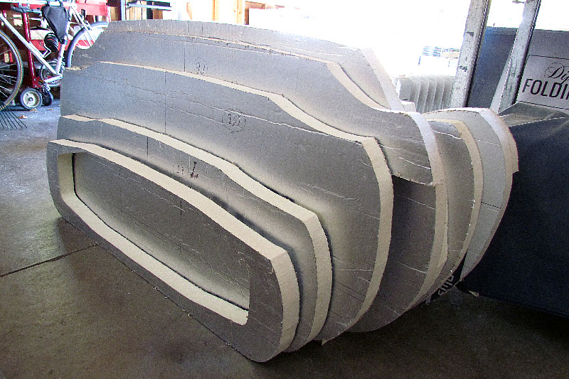
3rd ROW
The contours lined up. Sort of a compact car, accordion-folded.
(L) Compacted front view. Note the electric oil heater. I quickly discovered it would not even make a dent in the cold, and it was ONLY IN THE 40s!
(C) Compacted rear view
(R) And finally, the first width contour assembled onto the centerline contour.
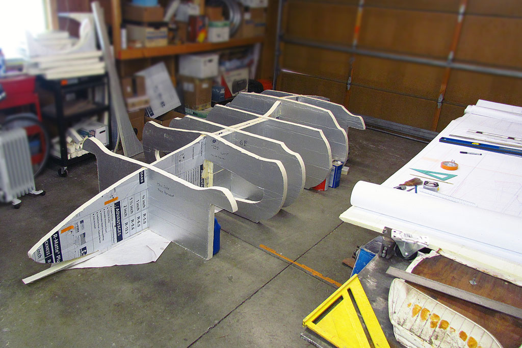
4th ROW
Coming together. Most of the contours in place, and then, all assembled in place.
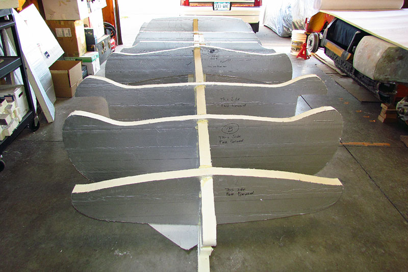
5th ROW
Views of them all. Even in the photos, it looks longer or narrower than the car is suppose to be! Then painting the actual contour edge red to help see it when sanding and shaping the foam.
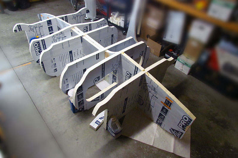
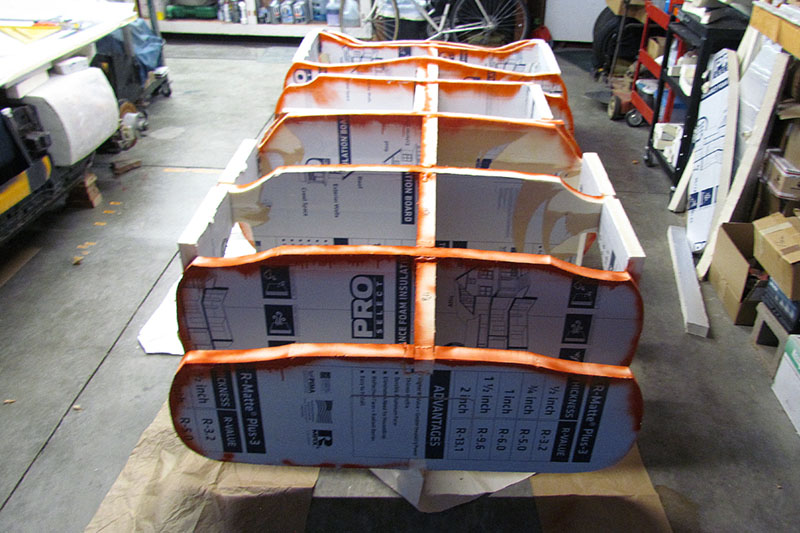
6th ROW
The painted contour edges give a better impression of the shape. Next up. . . fill 'er in.
December
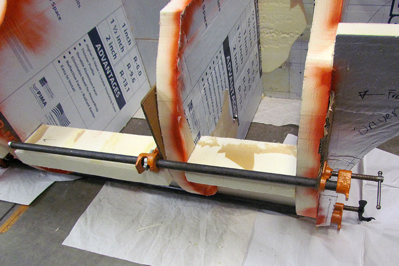
(L) Holiday prep slows down the work. I add spacers to strengthen the framing and to help hold panels in their cells. Every cell works together.
(C) With that in mind, I start at the door and will do the rear first. I still need to figure out in what order to add panels: verticals first, or horizontals, or ???