Contact: Rich Kurz Page content last updated January 1, 2026
The Construction Diary
2025
JANUARY
...wellll....two months. From Thanksgiving thru New Years, we were out of town, involved in unplanned family events. It was a mix of sorrow and joy.
With the new year, I picked up where I left off, and began vacuforming the intake louvres for the rear deck.
I completed the pattern before Thanksgiving.
Because this is a short-run, one-off production run, I did not invest the time in producing a vacuformer.
So I set up a manual version...a very crude one... and began learning how to make it produce what I wanted.
My solution involved placing an old radiant heater under the frame holding the sheet of styrene, and also heating it from above with a hot-air hairdryer-type paint remover.
I then quickly transferred it to the pattern and pulled it down over the edges of the mounting box and turned on my shopvac.
Often I also needed to continue heating the styrene using the paint remover to allow the suction to pull it down around the pattern.
I was able to turn out about four an hour once I got it down.
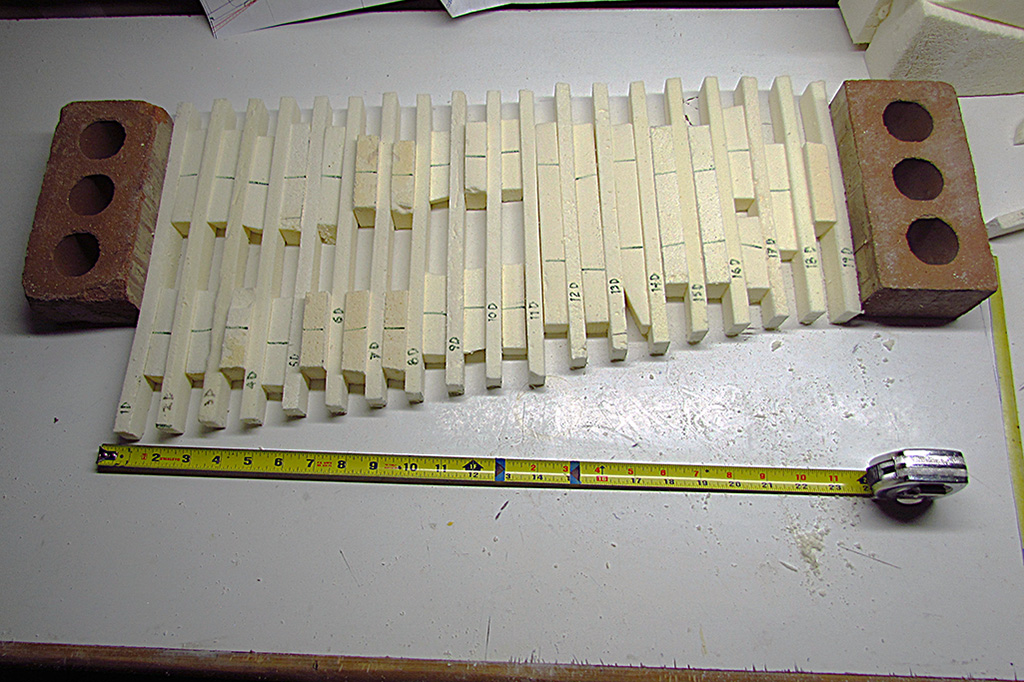
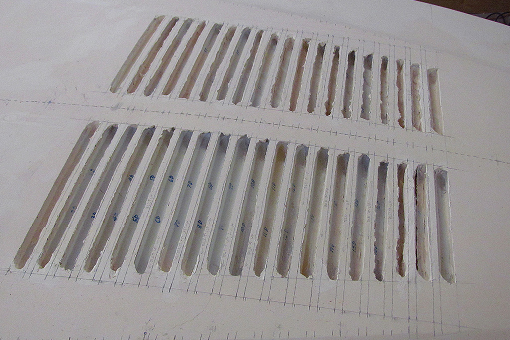
When I had enough pulls, I cut them out of the styrene sheet and trimmed them to shape with a straight edge on the pattern.
They were then cut in half and placed in a louvre location on the foam body rear deck in the grooves I had dug out over a year ago.
I marked where they overlapped, and then cut the overlapped half at that point and used the overlap excess piece as a backing when I glued the two halves together.
That all worked and the seam between the glued halves still needed sanding and maybe some filler, so on to the next step.
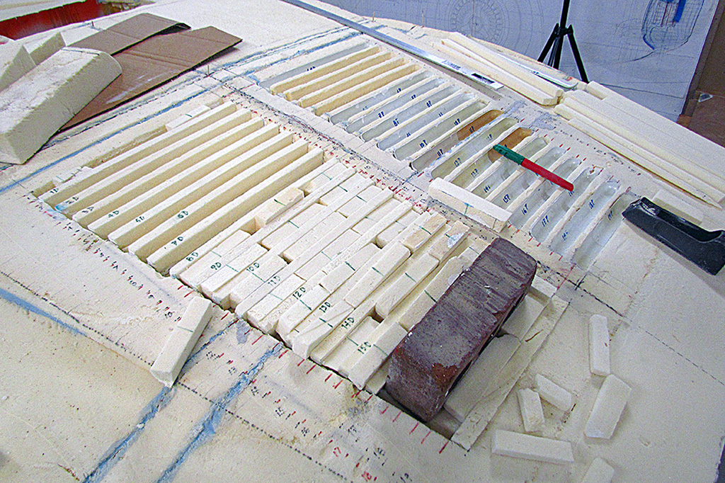
The next step started by glueing the louvres into place.
I decided to use acrylic Gesso, like that used on artist canvases, and then putty the gaps left by the rounded corners.
After nearly completing one side, I had to confront the fact that the dividers between the louvres were all of varying widths, and almost none of them the correct width.
I started removing the worst offenders, which left the lesser offenders, which then became the new worst offenders.
Finally, I admitted that I would have to start anew and remove everything and start with a recessed area and make new dividers and correctly place them.
Ugh.
So I began cutting and shaping new dividers plus spacers to use between them when I glued them in place.
Meanwhile, inbetween glueing the louvres in place, I cut out the base plates for the nose emblem and the tailpipe exits and glued them to the foam body.
Once the louvres are done, I will be ready to do the final shaping of the body.
Then my back went out the last week of January.
FEBRUARY
Another irregularity I had to confront while doing the louvres was an inexactitude about left and right side measurements relative to the tip of the nose.
I discovered this again when I tried to trace the curved line across the rear deck so I could use that to locate my louvre spacing.
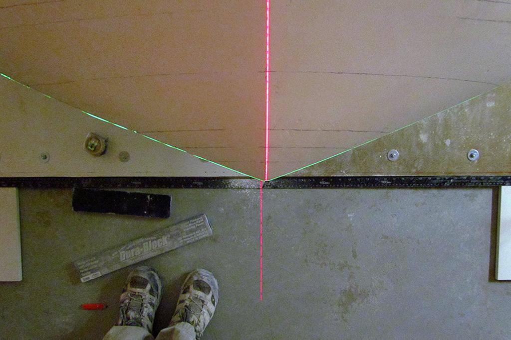
I found that my left-to-right line was NOT perpendicular to the centerline - in fact it was off by 1/2"!
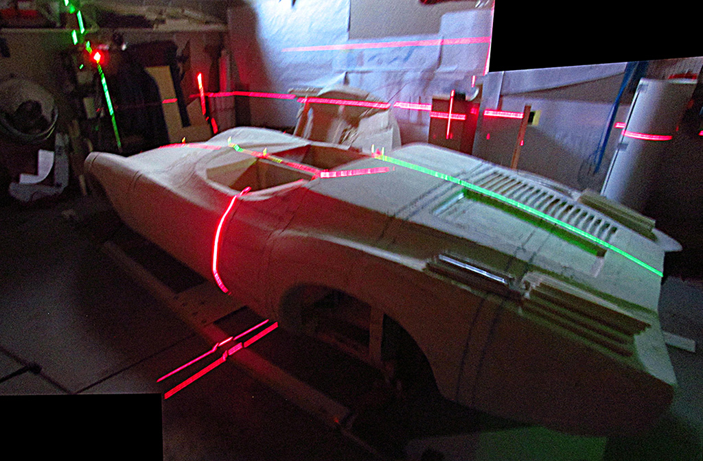
So I spent an afternoon reestablishing a correct centerline, matching what I had previously found,
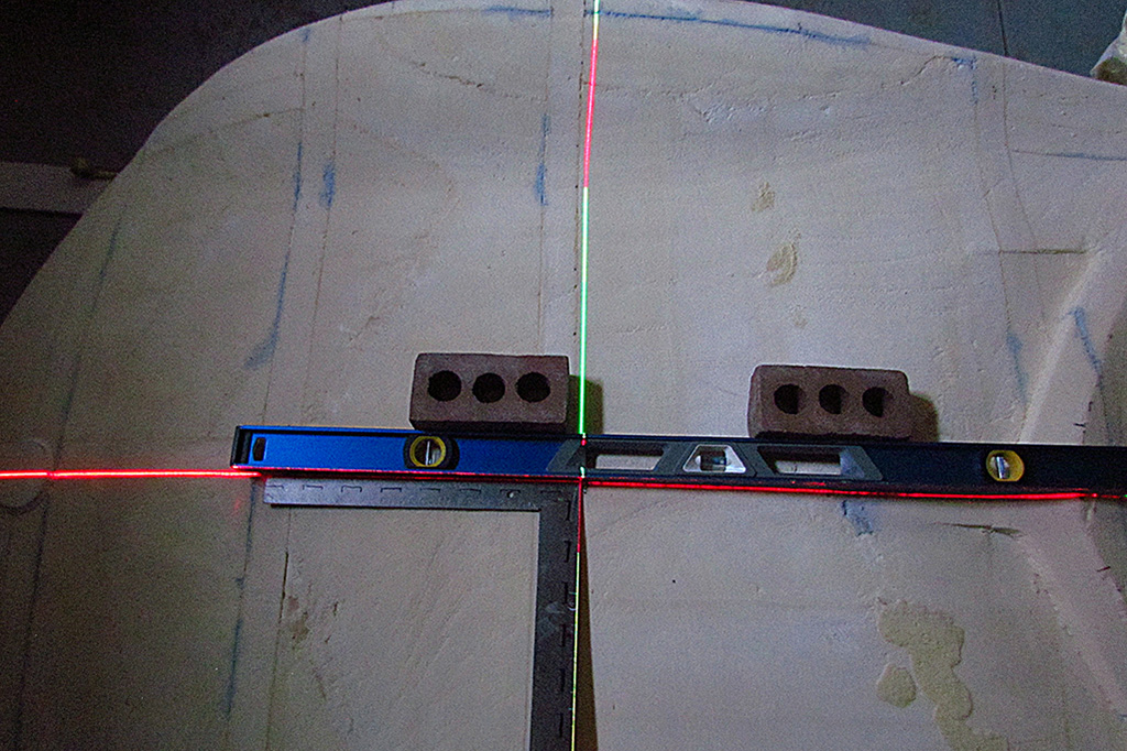
and then laid a steel right-angle on the flat area in the cabin opening to determine an exact right angle to the centerline.
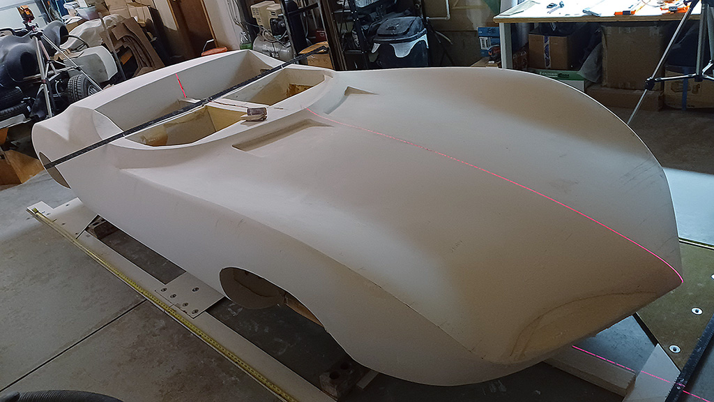
I then cast a laser level line from the driver side along the perpendicular arm of the rightangle.
Then I cast a laser line from the passenger side to align directly to the driver side laser line.
Then I could mark where those two lines fell on my tape measures on each side of the foam body on the floor.
Then I could measure equally forward and backward along the body to fix my measuring points.
Using a bubble level, I established where the nose tip was on the floor, and using my now-aligned tape measures, set where the zero-point was from the front of the car.
Remember that I have two datum points along the length that I measure from: the nose tip (0") and the rear axle centerpoint (127" from the nose).
I finished out the month working on the louvres on the rear deck, and adding to the gastank patterns to get as much volume out of their space as I can.
I still intend to make a fiberglass mold and parts of them as practice before covering the foam body.
SIDEBAR: Books I Found Along The Way
I began this project from the inspiration of just one article, the August 1963 issue of "Road&Track".
When I embarked on this project, I only had on hand, or access to, a few articles and photos in magazines and books.
The only hard info I had were the articles in "Road&Track" and "Car&Driver" from 1963.
I learned so much more along the way, and nearly all I know about making a car came from people and resources on the web... and in books.
Here are the magazines with the articles on the Monza SS. I treasured the first one for decades:
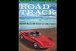


(L) The August 1963 issue that started it all for me.
(C) The September '63 issue with a 2-page spread on the Monza GT and SS.
(R) The December '63 issue that provided drawings on how the production versions might look like.
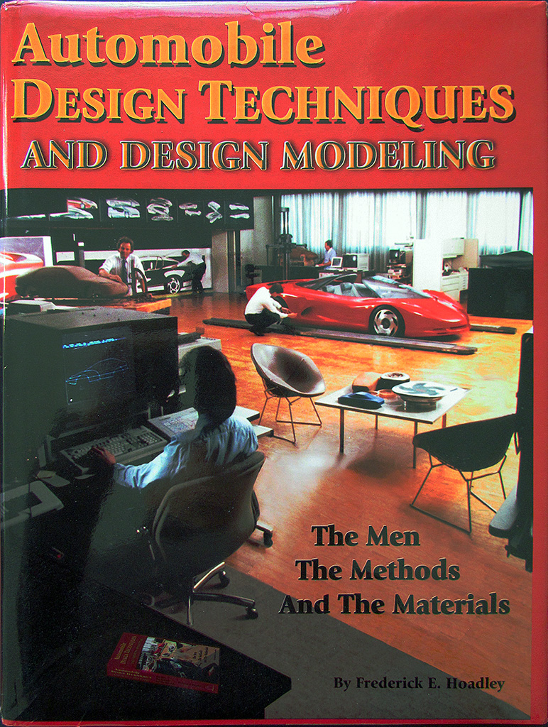
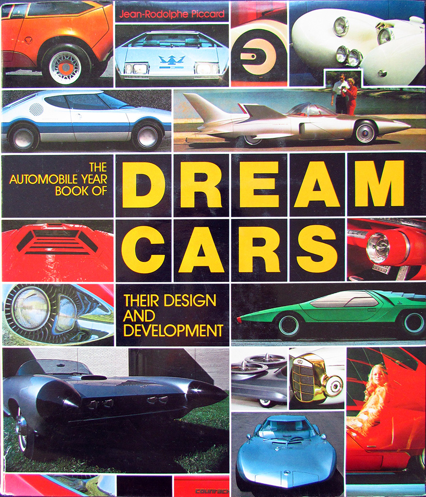
Here are some books I wished I had known about before I began my project.
These hard-cover books are for both education and entertainment:
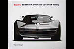

(L) This is the best compendium of GM's XP-series concept cars.
Check out the xp777 Monza GT and xp782 Monza SS.
Written and published by Roy Lonberger, designer of the xp842 Astro I progenitor, the X1000.
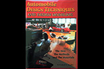
(C) This is a great reference book, and a sleeper, on how a presentation mockup vehicle is produced.
(R) I bought this new in '83. It's a good reference of the show cars from the '50s thru '80s.
Check back here... I will add more as I find 'em!
MARCH - APRIL
I got the louvres all glued back into place.
I will wait until I reach them again in the next step before I trim them.
I finally decided how to approach the last step, the final shaping and hard surfacing.
I have seen areas where I know I will need to build up the surface.
I will make a new set of surface contours to check my work and to guide the final surfacing.
It will be a two-part process to surface it.
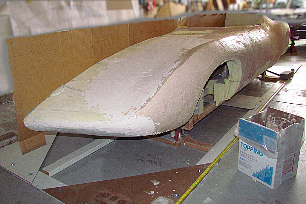
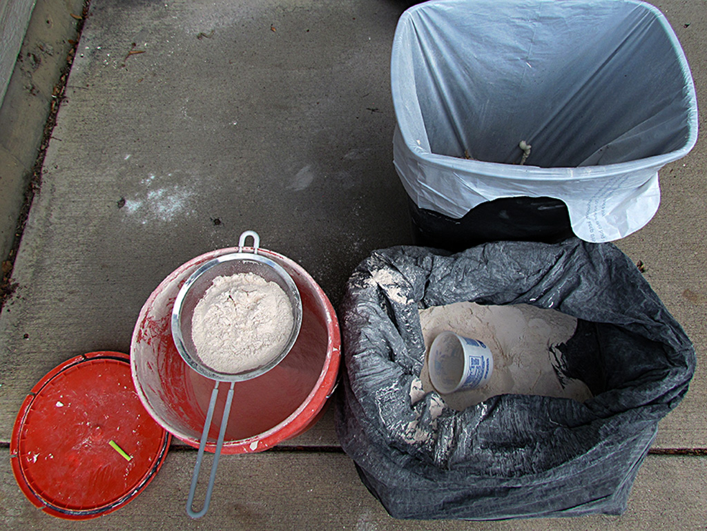
First, I will coat it and build out the surfaces to their final shape with joint compound.
It was recommended to me to use a type called "topping" that may be more flexible when dry (or drying).
It is like plaster, and about as heavy wet, but I think it dries lighter.
In any case, it is easy to apply and fairly easy to smooth out, and very easy to sand down.
A 150 grit takes things down quickly and controllably.
Once I have the final shape in topping, THEN I will apply the single layer of fiberglass and finish that with a skim coat of Bondo material.
The question is... how long will it take to get there.
As it turns out, I can only apply a coating of topping about 1/8" thick max, and that takes at least a full day to dry.
Some contours will require from 1/4" to 1/2", so this will take some time.
On the first pass, at best, I can cover half of the body.
You can do the math.
Well, the first thing is to dig out all my contours and decide on the best ones.
The most recent are the best, but are they really accurate?
It has always been a conundrum that the set of points from my 2016 visit and my 2019 visit differ.
I tried to average them out by including all of them in my Photomodeler file.
Yet, still, I could see two sets of points.
And the 2019 set sits higher (slightly out) from the 2016 set.
I surfaced the digital model to the 2019 set, and it did appear much like the actual car.
But my older contours are all to the 2016 set.
Ergo, I need to create a new set of contours and a new drawing to tack them out from.
And so I create a new tacking poster and begin a new set of files.
And sure enough, when placed on the car, it shows I need to fill out the body - up to 1/2" in places, especially on the sides.
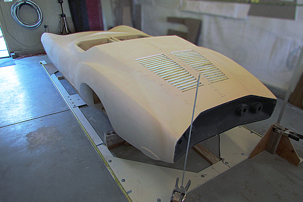
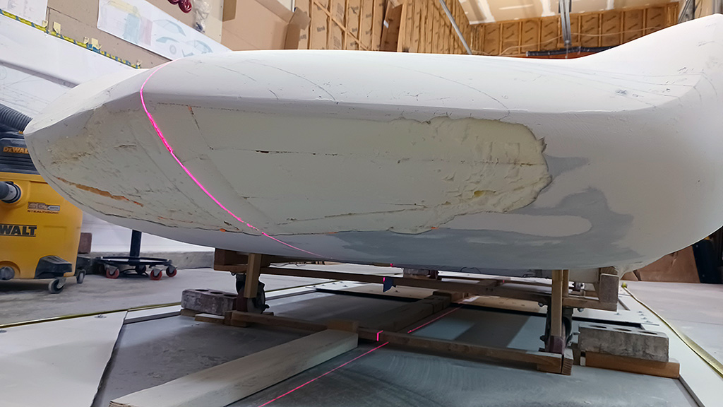
With new contours to direct me, I breathed deeply and began to apply the topping onto the foam body.
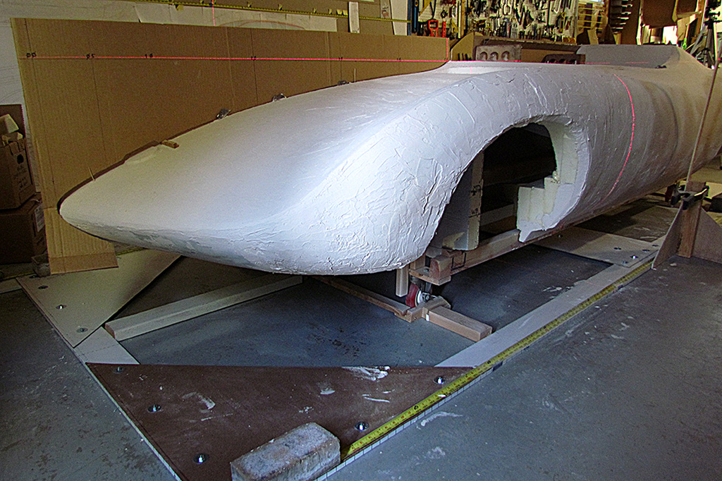
To my surprise and pleasure, with a uniform coat of topping covering the foam with all its seams and gouges, the body looks like a real car body!
I can see the car REALLY come to life!
And with each coat, it looks more and more like the real article!!
But this is going to be a time-consuming, tedious process.
And the end result will be worth the effort I put into it now.
And if I keep plugging away, a few hours each day, it...will...happen.
MAY - JUNE
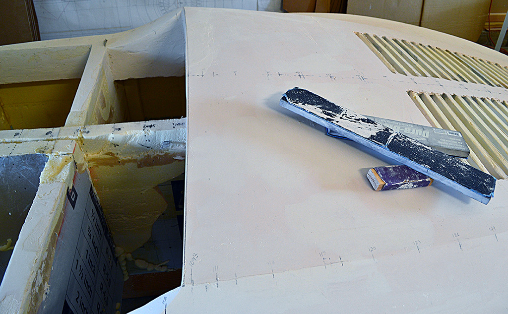
I build up enough plaster to do contour checks with the new contour guides.
Around the beginning of the rear deck, where the rear cut line of the door will be, the contours are quite close.
I then focus on establishing the ridge lines for the rear deck and the rear fenders, as well as the front centerline.
It becomes an interative process: Measure and mark the points, sand down to the height of a point, then sand in the point, redraw the points, sand into the point for width, then repeat the process.
I run into the foam base when sanding the rear deck down to the edge of the Kamm outline.
I decide to cut away 2 inches of foam and fill it with plaster.
This requires about four applications of plaster to build it up.
I keep slathering all around the body in preparation for future carving, but decide subsequently to focus of the rear deck and fenders before moving around.
Just the same, I do keep building up the front centerline contour after discovering it is mostly too low.
After doing a couple iterations on the rear deck (measure, slather, measure, slather), I discover I have about a 1/16" to 1/8" discrepancy vertically at different places around the body.
This is too much of an error, so I identify the problem stemming from having to move my laser all around the body and trusting it all lines up when I cast the midline all around the body.
It is off by 1/16" by the time the end meets the beginning, but if it is off, can I trust even that measurement?!
In addition, my wooden yardsticks that I use for vertical measurements don't line up when they are placed head to tail next to each other.
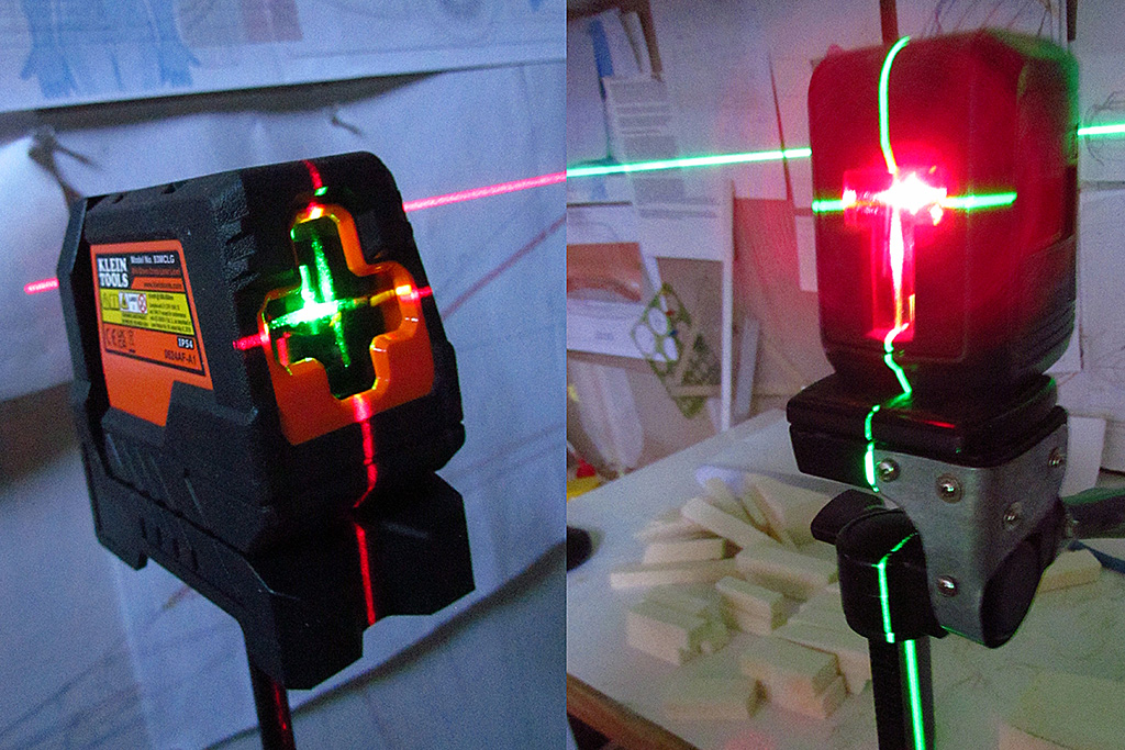
So I buy two more lasers and a half dozen metal yardsticks that DO line up.
I position a laser at the midpoint of the driver side, and the other two at the front and rear-right quarters of the passenger side.
When the lasers are lined up, there is no more gap on the midline!
I have established the midline plane as my zero-point datum.
I glue two yardsticks together so I can read it front and back without turning it around.
The measurements become consistent and trustworthy.
But it still takes an hour or two to remark all the points before I can cast laser lines.
Another laser that can be moved around first measures the heights of my marks on the vertical yardstick.
Another yardstick on top of the body measures how far out the marks are from a laser-cast centerline.
Did I say it is tedious?!!
But it does work, and as I sand down and build up the rear deck and fenders, the car truly looks more and more like the original, as checked visually against my photos.
JULY - AUGUST
I continue now moving to the rear fender vertical surfaces.
Again I sand down to the foam and create more gouges that need filling.
I built those up and do the iterative process of measure-sand-slather.
Next I begin refining the cabin outline.
To avoid more gouges, I decide to dig out the foam behind the outline and fill it with sandable plaster.
But one section on the driver side is to thin and crumbles away without the foam backing.
It creates a deteriorated section about a foot long.
This requires a couple weeks to slather-dry-slather-dry.
Meanwhile, the buildup on the front centerline continues and can be sanded to shape, according to a contour guide.
With the cabin outline established, I can now locate the intake vents in front of it.
This turns out to be a trial and error procedure.
I end up finding a photo that looks at it from the front and another from the side.
After laying out what I measure off the photos, I tweak it comparing it to the photos by my eye.
The rear deck is stable dimensionally and only needs to fill some gouges.
So I begin on the front top surface and do slather-measure-sand a few times.
The last adventure is to take the plaster powder I have vacuumed up and add water to make it into plaster again.
This works and has nearly the same consistency as new plaster.
When applied and it dries, the surface has a slight rough texture.
But after letting it sit a week in the bucket, I discover it has grown mold on the exposed surface.
I simply toss the entire bucket, both bucket and all, and go buy a good new box of topping.
I won't do that again.
SEPTEMBER - OCTOBER
Reviewing my photos, I see one that if I can color correct, may give me an idea of the original color of the MonzaSS.
This would be circa 1965+ because the car has the rollbar.
I correct the color so that the dormant grass looks about the right shade.
That is somewhat difficult because of the color shaing due to the multi-colored awining over the car display.
Then I try adding increasing amounts of color saturation.
The image shows three variations of saturation.
All in all, the color looks orange-red, which is the base color of the current paint, but the modern paint (since the early 2000s) has a special metallic pearlescence.
I finish up the rear deck by establishing the mildly curved edge behind the seats.
Then I begin working on the sides between the wheels, and the front top surface (it's not a hood, but it doesn't sound right to call it a trunk either.)
Then, at long last, I begin finishing the strakes between the engine intake louvres.
I try to make a straight edge along the strakes by inserting a piece of wax paper backed by a piece of foam.
The wax paper is used because it should pull free fom the plaster and leave the plaster in place, which it does starting when the plaster is soft like clay.
That works for two latherings, but starts failing on the 3rd and 4th.
So I remove the inserts and add plaster on top and smooth it with a clay sculpting tool.
It appears I will need to fill in the louvres because they are now too deep, in addition to the final shaping.
At this point, I take stock and decide that I have a good chance to finish the sculpting of the body by Thanksgiving - and maybe even two weeks before.
I double my time in the garage.
I need to complete the rear underpan, the front nose and underpan, which was what I first did in July '22, the rear deck intake louvres, and the shaping of the wheelwells.
Then to check the overall body for smoothness and then apply the surface hardener.
And maybe complete the poptop and make glazing patterns for molding.
I continue working the louvres and raising the surfaces that were too low.
I slowly realize that the strakes between the louvres, and therefore the louvres I inserted, do not evenly line up left-to-right.
I will also have to establish the outside edges of the louvres.
These louvres are going to be a bear, I can see.
While I am at it, I also do a quick check of the upper body where the rear deck begins, generally following the rear cut line of the door.
Yup. They match.
NOVEMBER - DECEMBER
Because slathered plaster takes at least a day to dry enough to sand, while it sets on one end of the body, I can work on the other.
I begin the refinement of the nose by re-establishing the front fender ridges.
Yup (or 'Yipe'), they have shifted slightly as I worked the fenders.
The front "trunk" area needs building up on the passenger side and smoothing out of lumpiness on the driver side.
Add & subtract - add & subtract.
As I establish a new fender ridge, because it has moved a little outward and so needing to move-in a smidge, I also must reshape the sides of the fenders.
I get there and move onto the nose.
I am now two weeks into November.
As I check the contours of the nose, I have to admit it is all bloated.
A lot must come off, which means for the underpan, I must chip off the layer of Bondo I applied over three years ago and sand into the underlaying foam!
I thought the nose would only take two days, but I realize it will be at least a week.
And that means I cannot make my Thanksgiving deadline.
That takes the wind out of my sails, but I push for the deadline anyway.
But after Thanksgiving, I loose my pace and energy and am preoccupied by all the holiday prep and to-dos, and not much gets done.
I do more add-&-subtract for three times, but by New Years week, it looks like it should look, and I will be able to move on.
Meanwhile, back at the intakes and strakes, I face another setback.
The louvre inserts I glued in are over an inch deep by the time I sand the strakes down to shape.
And the strakes are still not well aligned.
I build up the strakes with plaster, and when dry, I grind them to shape with a Dremel sanding wheel and a metal guide.
3/4" seems to be correct to make rounded corners for the intake outline.
In the process of grinding, the vacuformed louvres just plain get in the way, and so I cut them and pull them out.
Just another good idea that needs more refinement.
To add plaster into the intakes and give it a concave shape, I cut a shape out of a plastic plastering tool.
It only generally gives a shape to the wet plaster, and so much must be added, that it will need 2 or 3 applications at least.
I put the first layer down pretty heavily, and it required a week plus a couple afternoons under a heat lamp to harden.
With the intakes and strakes being defined little by little, and the nose completed, what's next?
The wheel wells need their outline defined and the 1/2" bevel added around them.
The rear underpan looks pretty good, but must be checked and finished.
The intakes of course, and that will complete the basic sculpting.
Next will be surface checks for lumpiness/smoothness and for divots and pinholes and ragged edges.
Then, the application of the surface hardener.
And finally, adding foam panels to the inside of the body to reinforce it in preparation for traveling to the fiberglasser.
Oh - and I may well create the pattern for the 5" high front and side windscreens.
Definitly more to come...
Check out 2026 for more progress!
SIDEBAR: Books I Found Along The Way
I began this project from the inspiration of just one article, the August 1963 issue of "Road&Track". When I embarked on this project, I only had on hand, or access to, a few articles and photos in magazines and books. The only hard info I had were the articles in "Road&Track" and "Car&Driver" from 1963. I learned so much more along the way, and nearly all I know about making a car came from people and resources on the web... and in books.Here are the magazines with the articles on the Monza SS. I treasured the first one for decades:
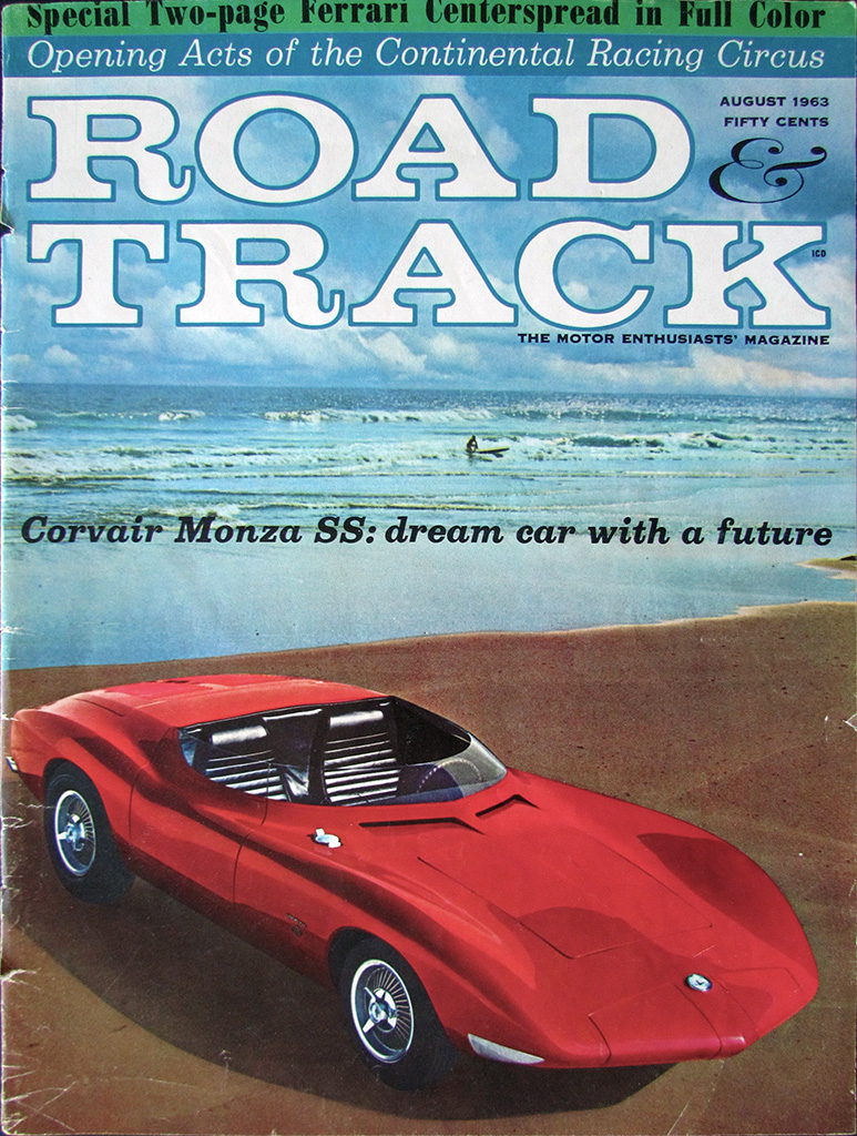


(L) The August 1963 issue that started it all for me.
(C) The September '63 issue with a 2-page spread on the Monza GT and SS.
(R) The December '63 issue that provided drawings on how the production versions might look like.
Here are some books I wished I had known about before I began my project. These hard-cover books are for both education and entertainment:
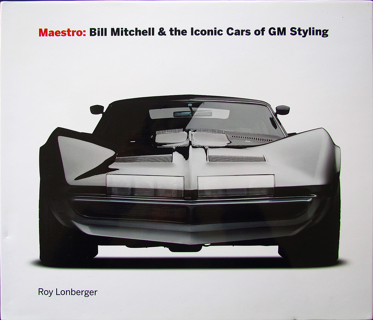
(L) This is the best compendium of GM's XP-series concept cars.
Check out the xp777 Monza GT and xp782 Monza SS.
Written and published by Roy Lonberger, designer of the xp842 Astro I progenitor, the X1000.
(C) This is a great reference book, and a sleeper, on how a presentation mockup vehicle is produced.
(R) I bought this new in '83. It's a good reference of the show cars from the '50s thru '80s.
Check back here... I will add more as I find 'em!
The Build - 2025
January
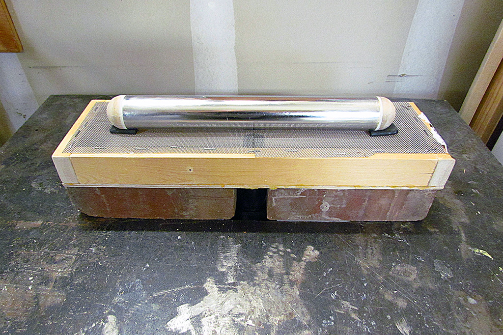
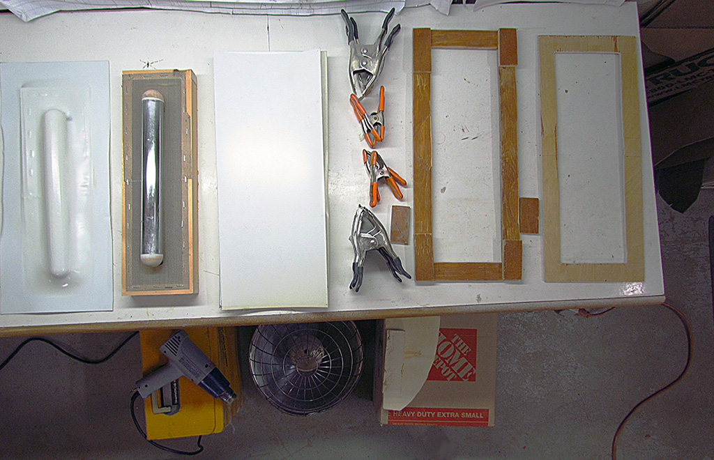

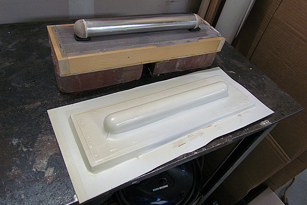

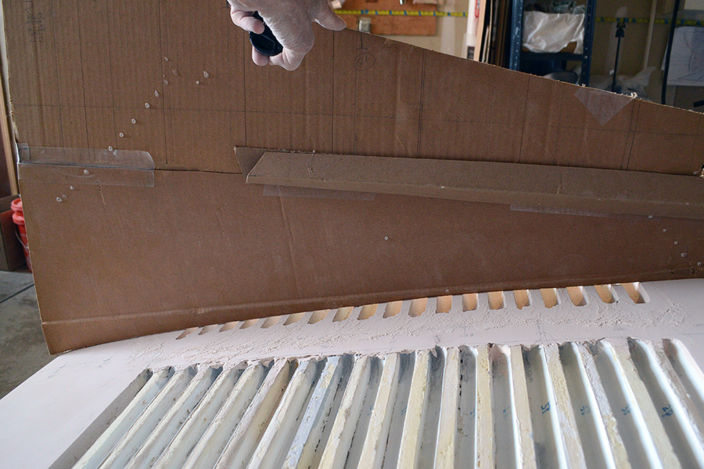
1st ROW - Creating the Louvre Pattern
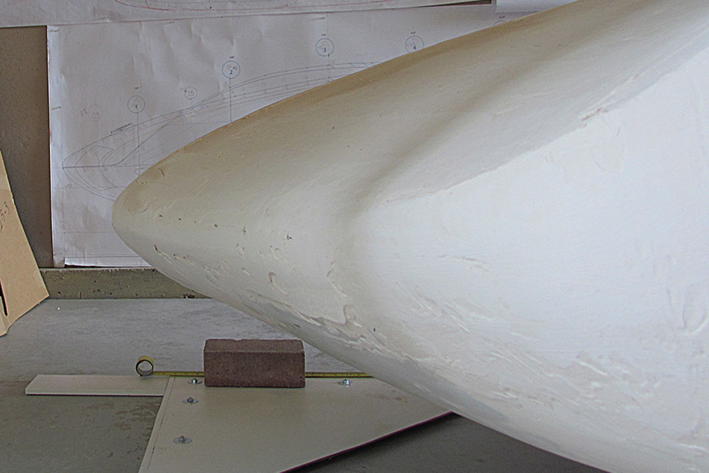
(L) The full-length louvre molding pattern on the vacuforming box.
(CL) The initial setup showing the vacuform box connected on the side to the shopvac hose.
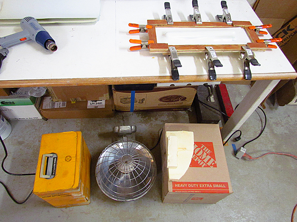
(CR) The setup of the radiant heater on the floor and the prepared styrene sheet holding frame.
(R) The frame mounted above the radiant heater.
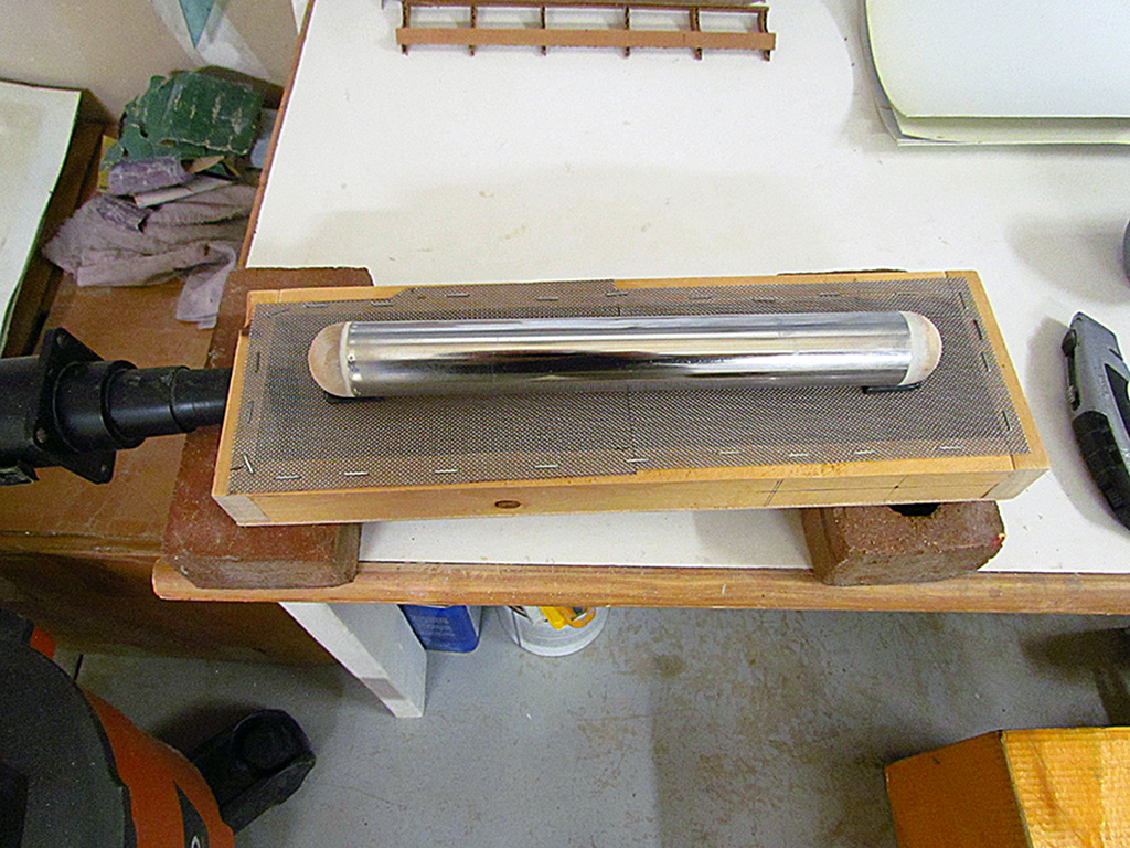
2nd ROW - Preparing the Vacuform Sheet
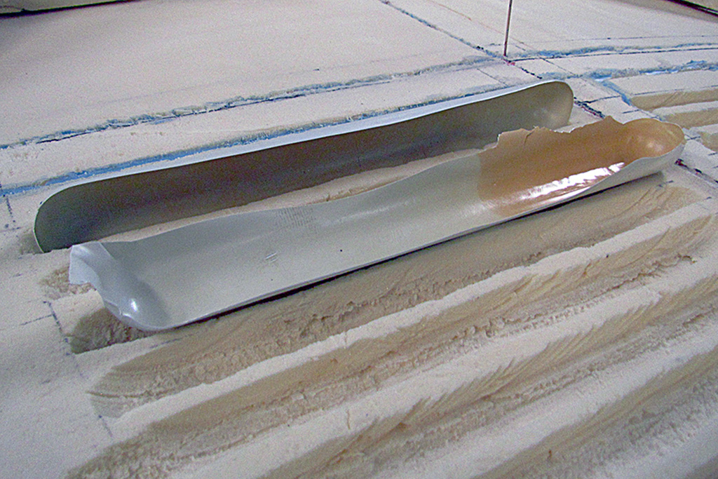
(L) The different pieces (and steps) from styrene sheet to formed piece.
(CL) A good pull! The styrene sheet over the pattern.
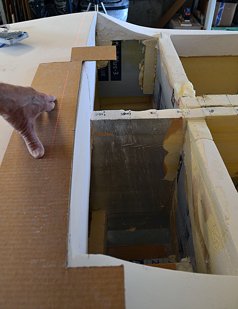
(CR) A look-down view of the same.
(R) The side hose interferred with the ability to pull down the framed sheet over the pattern. So I changed the shopvac hole from the side to the bottom and repositioned it on another table. That worked much better.
3rd ROW - Louvres Produced and Trimmed
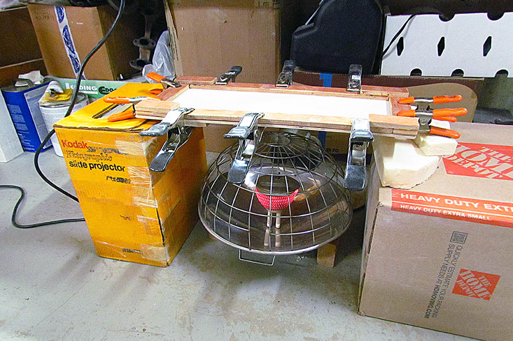
(L) Here is the actual setup to heat and then pull the vacuform part.
(CL) Here is one of the better parts, compared to the pattern.
(CR) The first couple of test pulls.
(R) Here are the louvres that have been cut apart and overlapped in preparation for glueing.
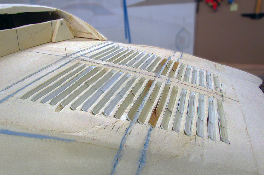
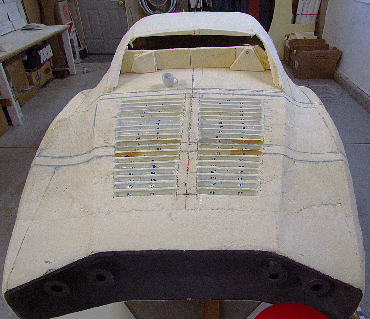
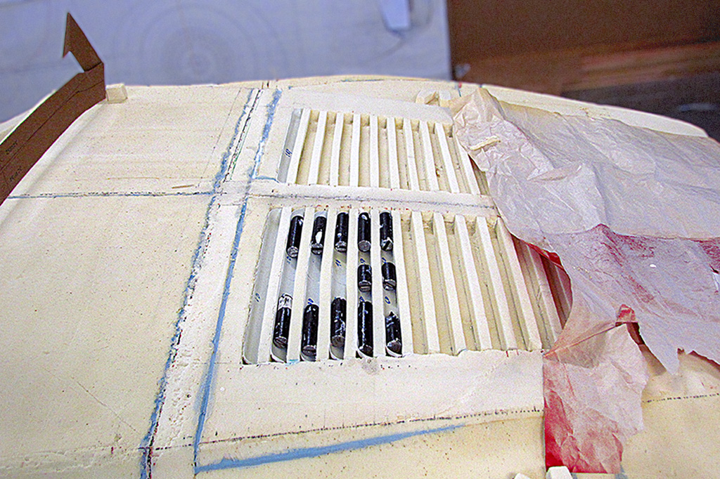
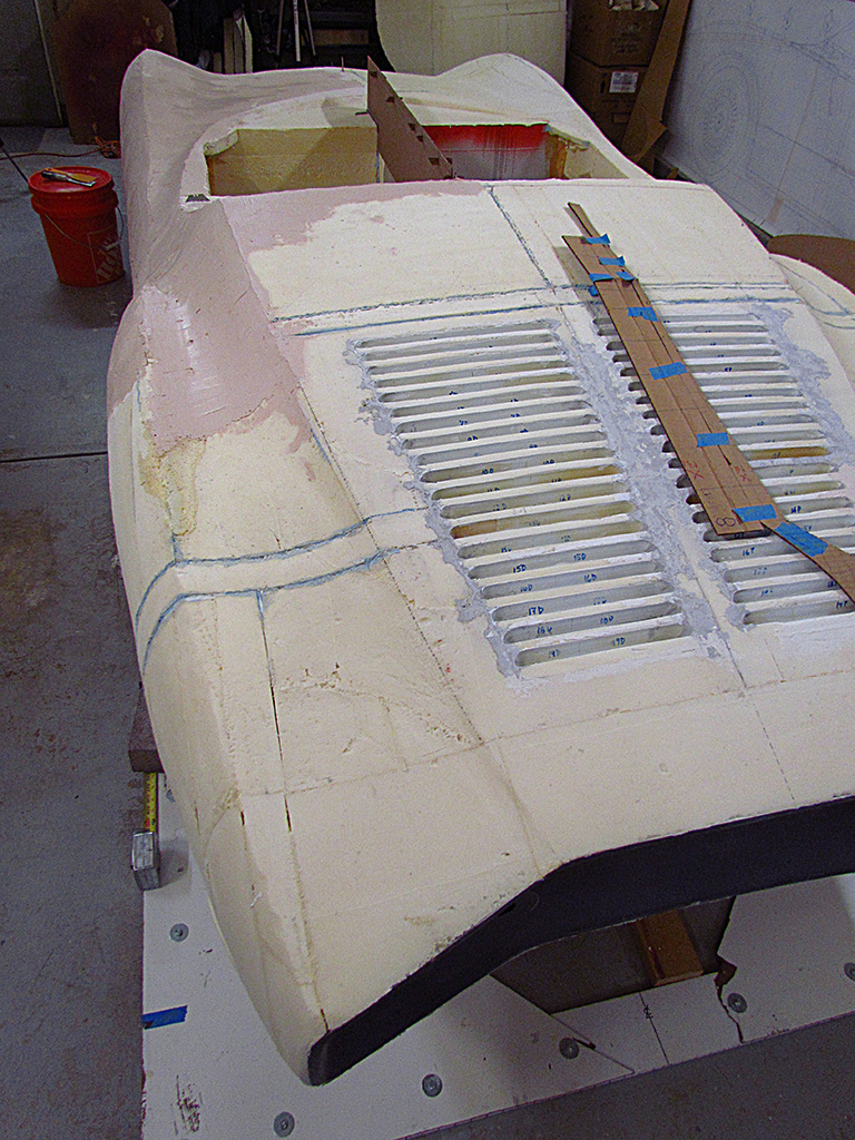
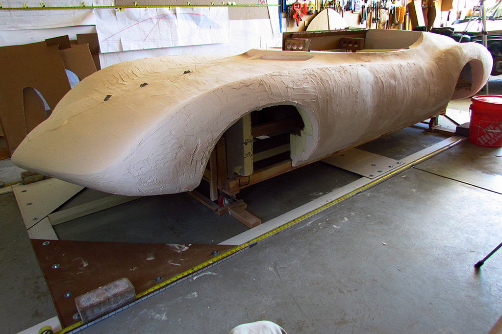
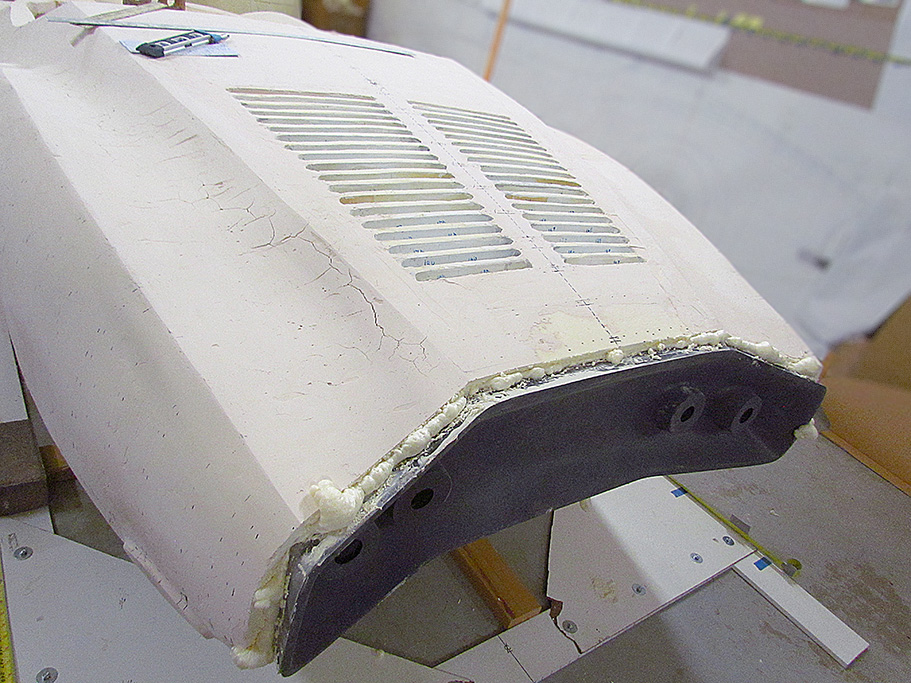
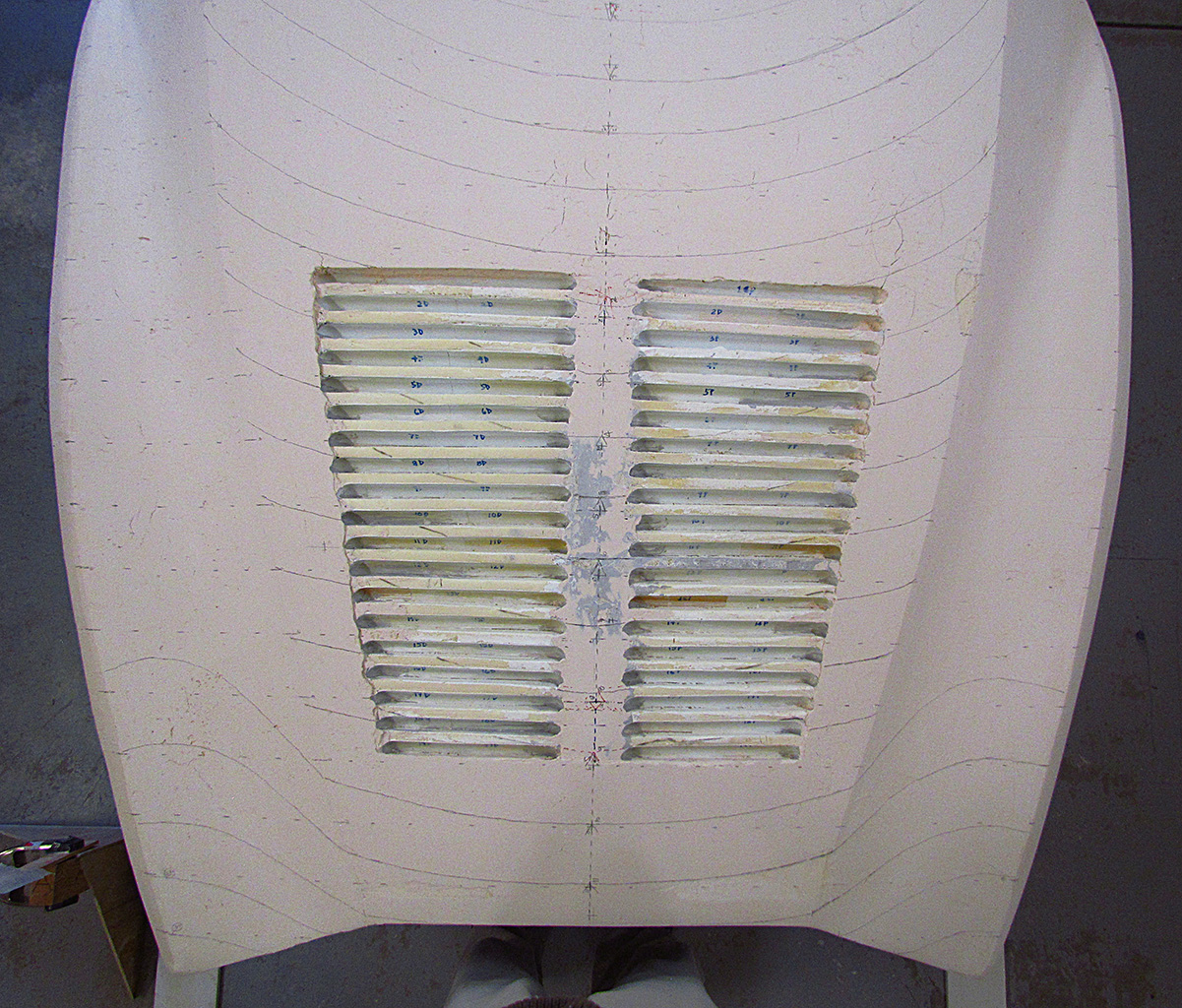
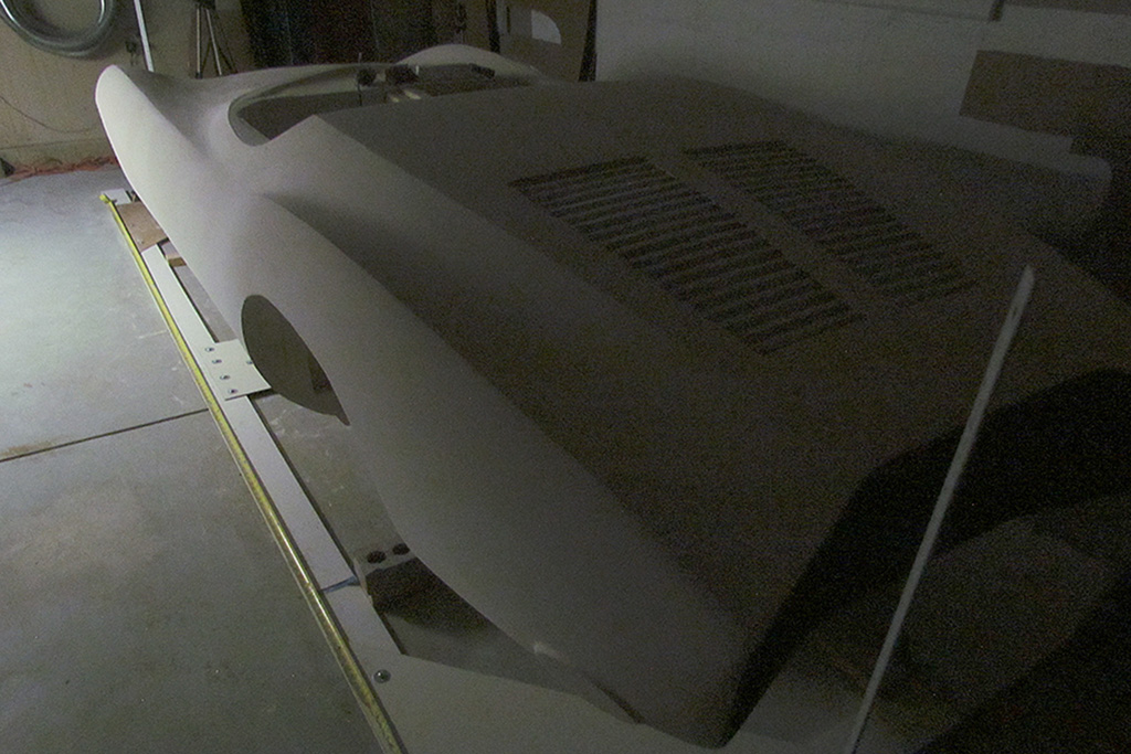
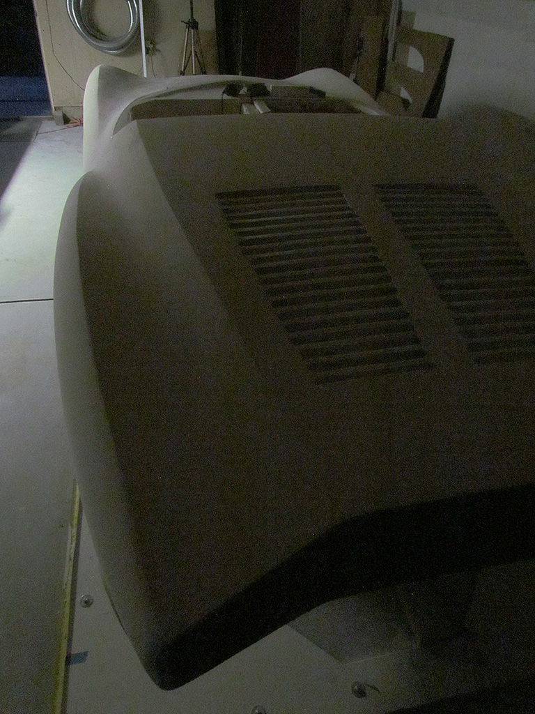
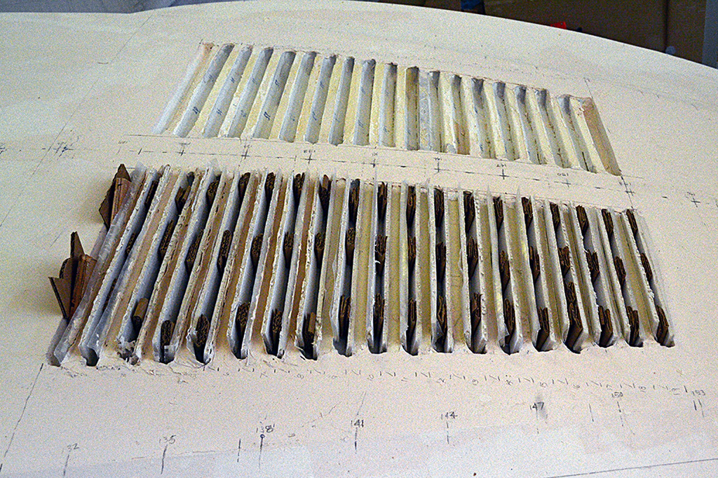
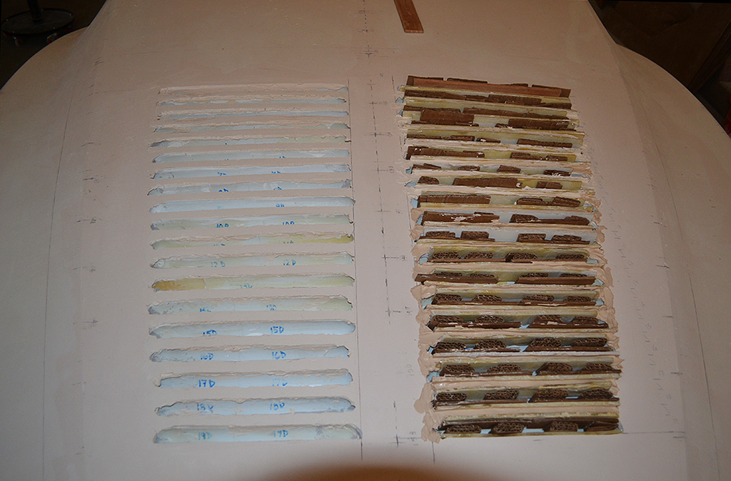
4th ROW - Louvres In Place
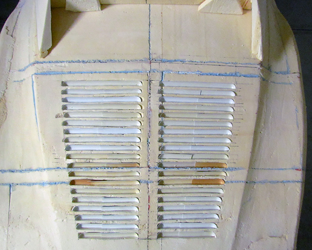
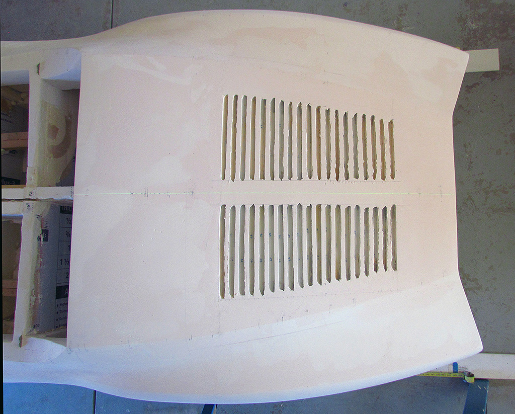
(L) First view of the louvres in situ with the original varying-width dividers.
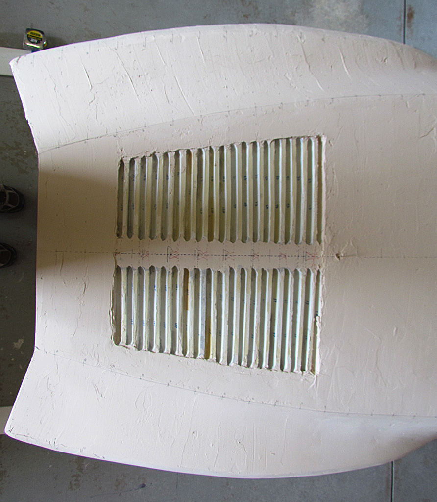
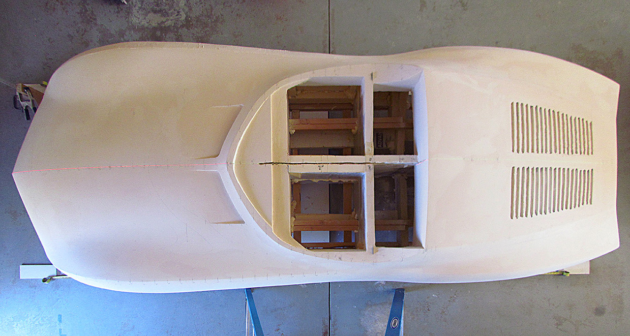
(C) View from above.
(R) A look-down view of the same.
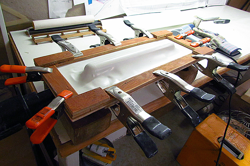
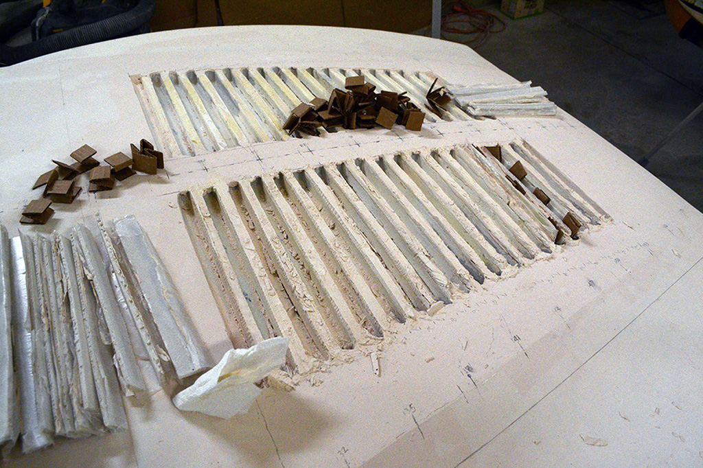
5th ROW - Louvres Glued in Place
(L) Louvres being glued in place a half-dozen at a time and held in place with solid pipe weights.
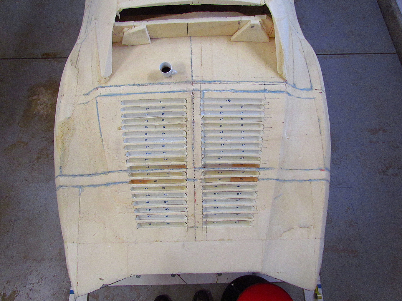
(CL) A look-down view before they were glued in place.
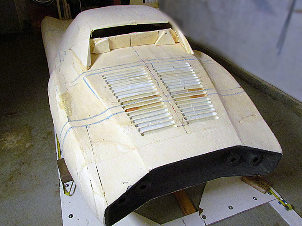
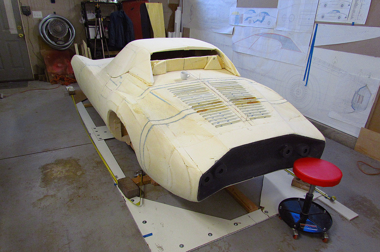
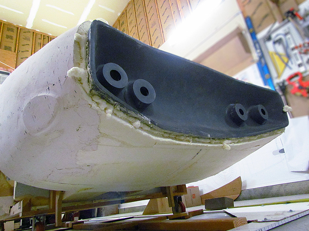
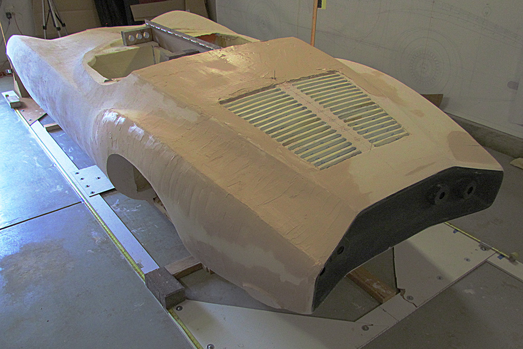
(CR) A 3/4 rear view of the unglued louvres.
(R) And a rear-view of the same.
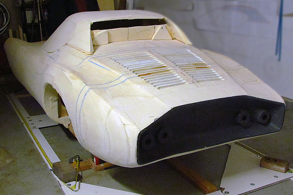
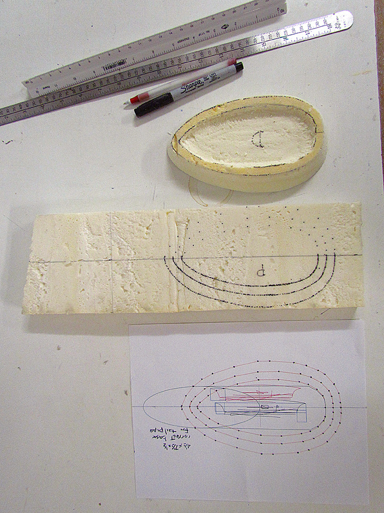
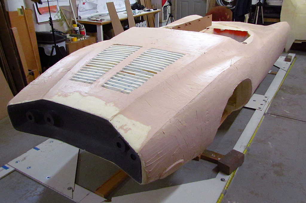
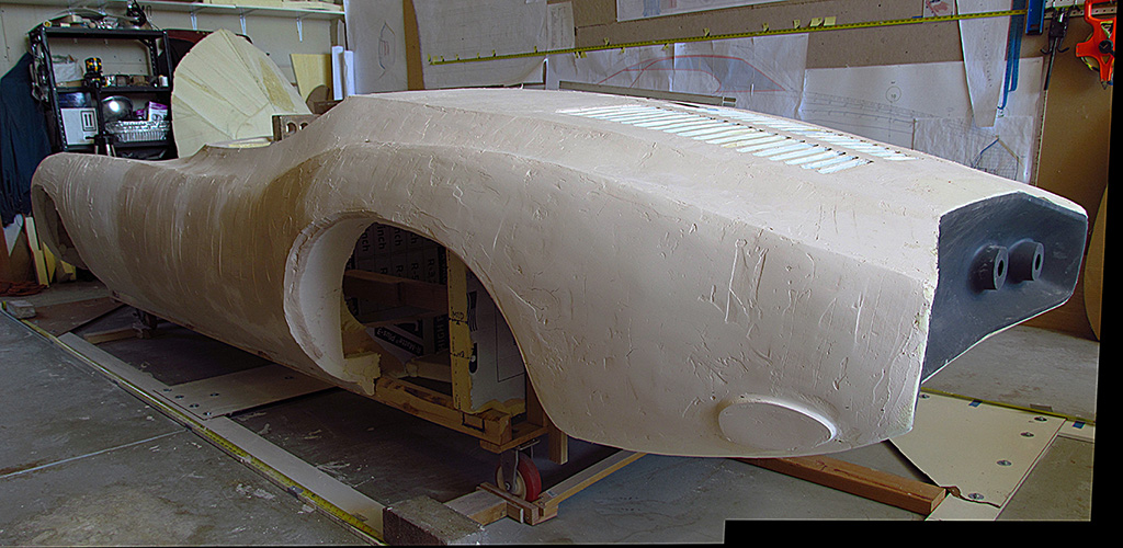
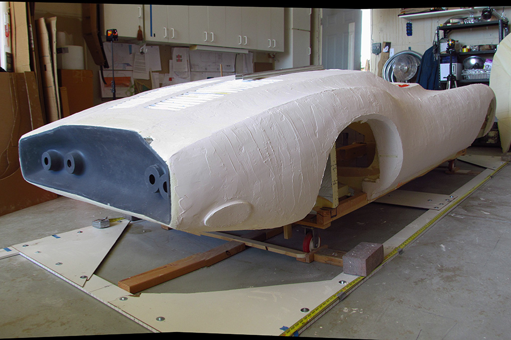
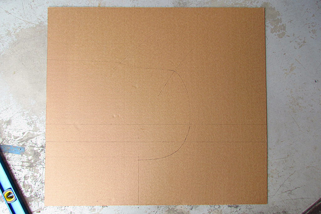
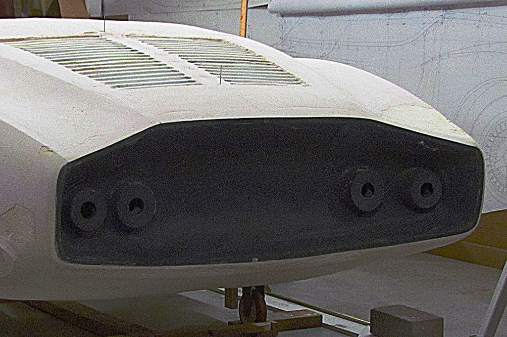
6th ROW - Nose Emblem and Tailpipe Bases
(L) The drawing of the bases was derived from my master drawing.
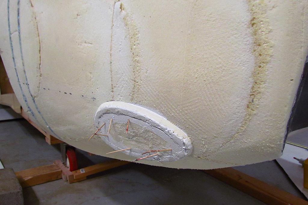
(CL) The driver-side tailpipe base in place.
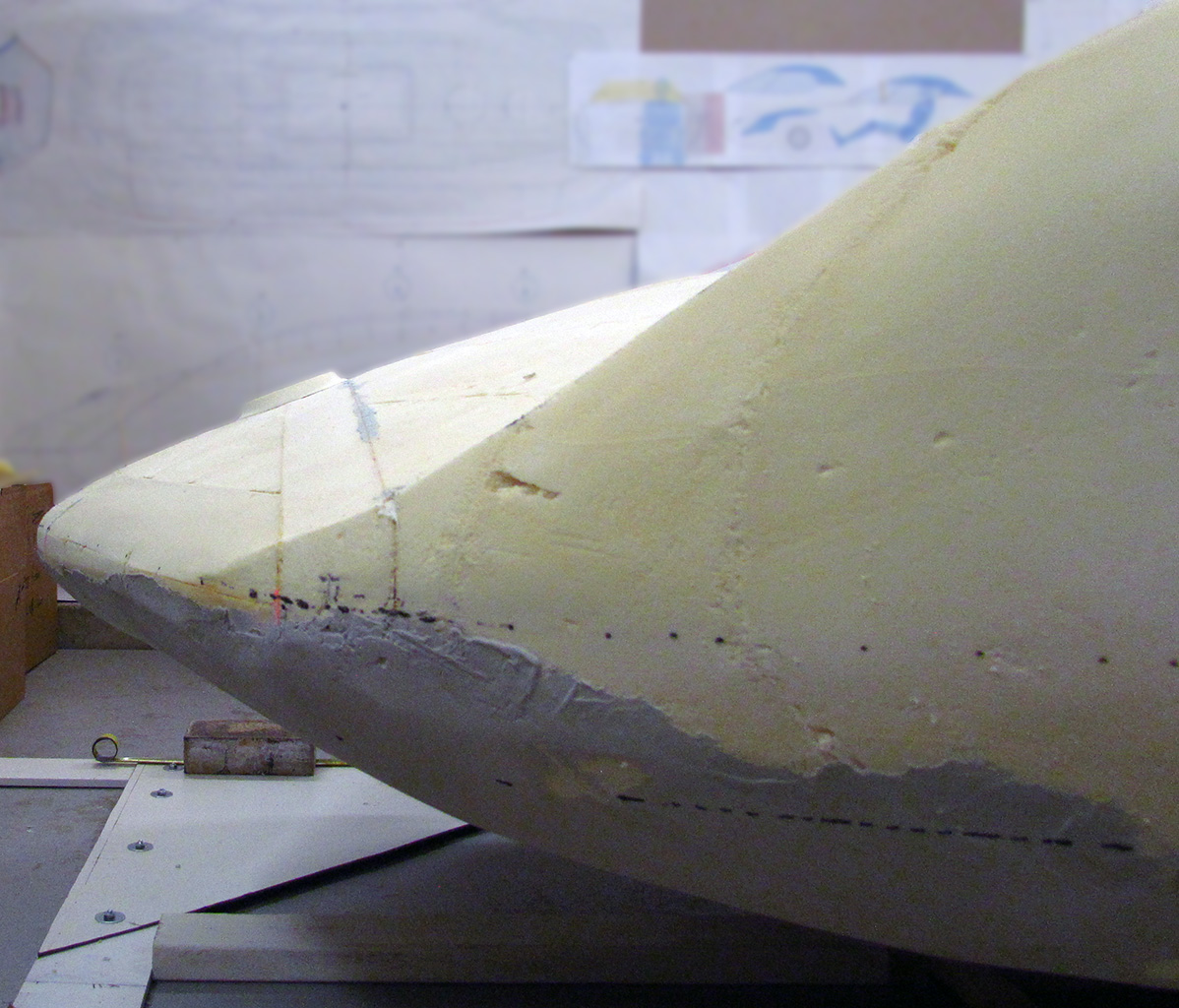
(CR) Side view showing the placed nose emblem.
(R) 3/4 front view showing the new nose emblem base as placed.
February

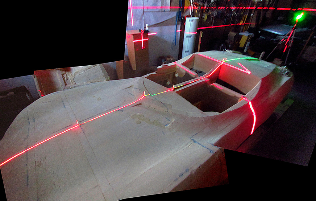

1st ROW - Reestablishing the Centerline
(L) The centerline and the perpendicular laser lines as projected.
(C) The centerline is confirmed by the placed toothpicks along the centerline and by the front red and rear green lasers centered on each other.
(R) View from the passenger side.
2nd ROW - And the Perpendicular
(L) Looking at the perpendicular laser lines.
(C) Again, I laid a two-foot, right-angle along the laser centerline in the cabin area.
(R) I cast a new laser line along the 90-degree arem of the right-angle and another laser line from the other side so the two lasers centered on each other. That allowed me to establish marks on the floor frame that would be the same distance from the nose of the foam body. All I had to do is establish the location of the nose tip on the floor.
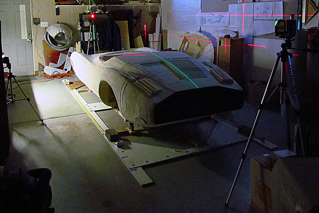
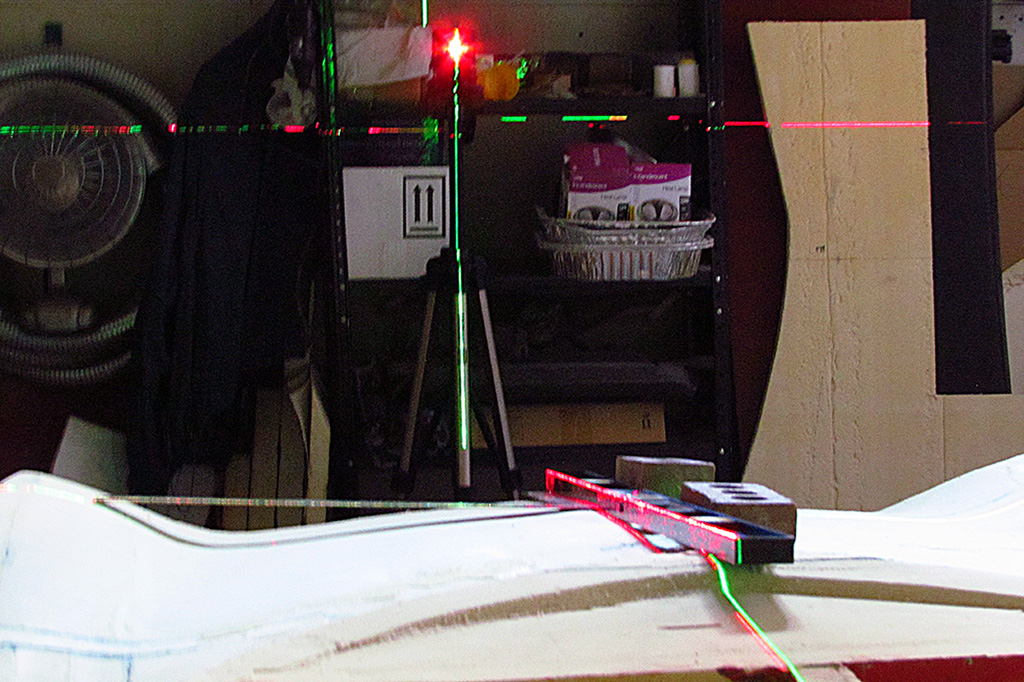
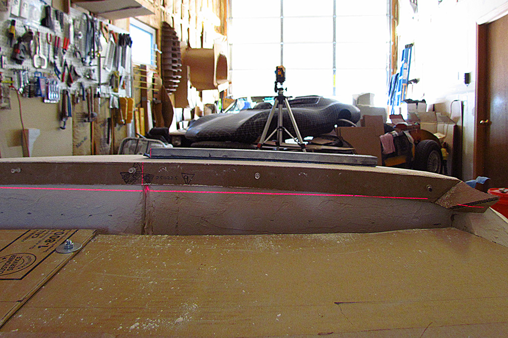
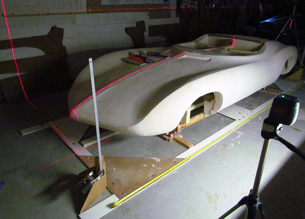
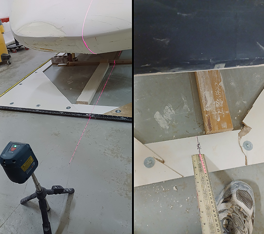
3rd ROW - Establishing Perpendiculars
(L) Here is the setup to align the front wheelbase...red laser in front, green on the right, and red on the left.
(CL) One check on aligning opposite lasers is for the vertical line to fall exactly over the aperture of the opposite laser, as we see here.
(CR) The front red laser establishes the centerline. The 2-foot right angle gives the perpendicular. And the side lasers align on it.
(R) The verticals of the opposite lasers also fall on tape measures, one on the floor and one on the garage wall about 3-1/2 feet up. The wall tape measure allows me to use just one laser to give me the contour placement. It shines onto the tape measure on both sides and onto the same dimension once this alignment is done. It is so much quicker establishing a new contour line when I go from contour to contour.
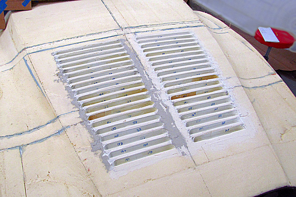
4th ROW - Louvres: 2nd Attempt
(L) Just a quick test to see if the new louvres and spacers will fit in the old space on the rear deck. They do.
(CL) Glueing in the second set of spacers. I can only do about a half dozen at a time before the alignment starts drifting.
(CR) Glueing in the louvers into each vent. I only do a half dozen at a time because that is as many weights as I cut out from a metal stake.
(R) All are in place. I do some filler putty at the quarter-round corners of the louvres.
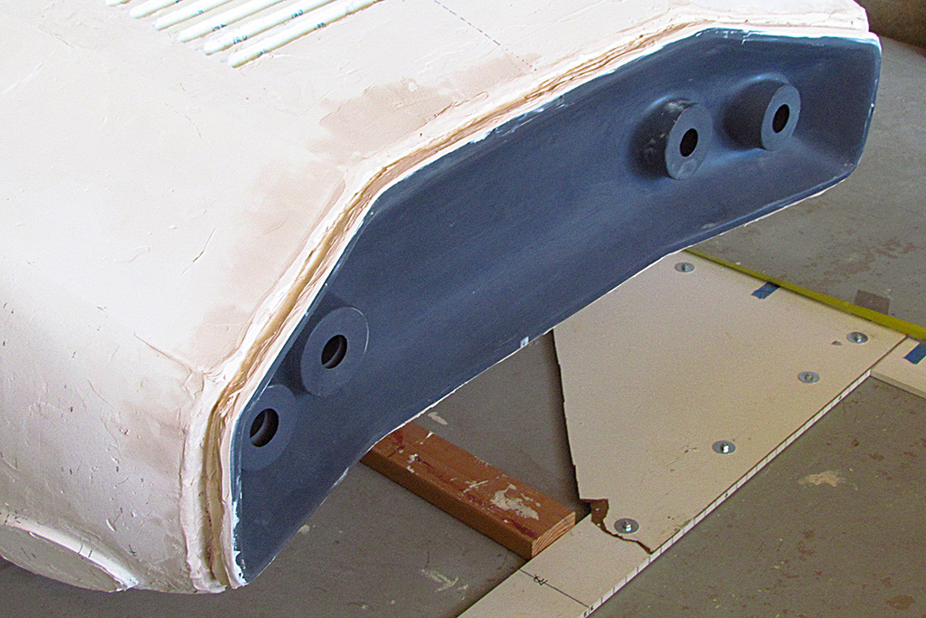
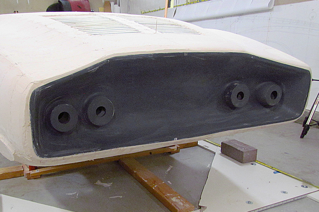
5th ROW - Louvres & Gas Tanks
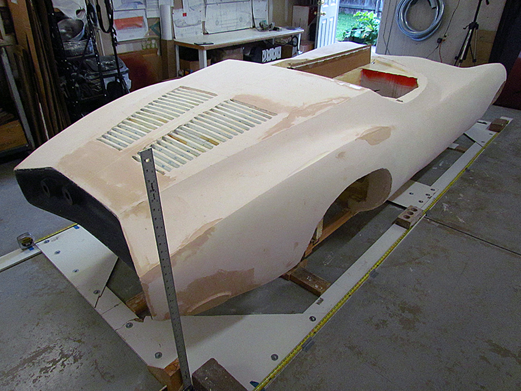
(L) A look-down view of the louvres. I will refine it when I do the topping stage.
(CL) The passenger gas tank needs only a small addition. The new additions will be bondoed and made smooth.
(CR) The driver gas tank was able to have more volume added.
(R) The
March-April


1st ROW - Rear Deck Contours
(L) Once the louvres were in place, I wanted to check the rear deck contour.
(CL) The contour does vary slightly from front to back.
(CR) Four in place and centered. Backlight shows where filler will be needed.
(R) A new contour for behind the seats, on top of the tacking poster.
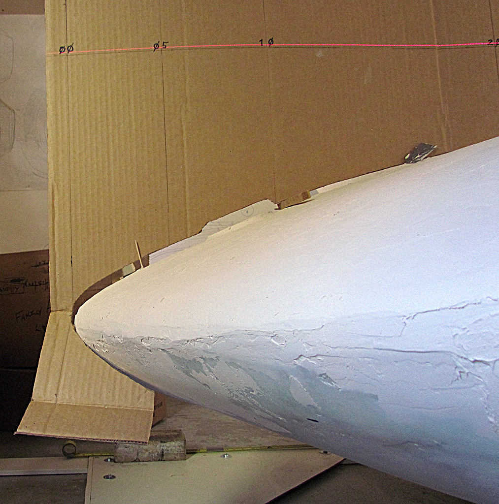
2nd ROW - Test-Fitting New Contours
(L) I quickly realized I needed something to hold the contour at the centerline and on the floor. Without that, I could not keep it parallel to the ground. So I added a center board and supports on the outside edge.
(CL) I also made a center contour for the nose. It seemed to indicate that the entire nose drooped down by about 1/4". Not enough for me to cut it and raise it back. It's good enough.
(CR) You can see the light coming under it.
(R) This is what it should look like.
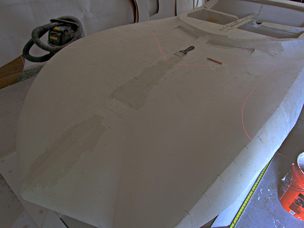
3rd ROW - Slathering
(L) First, I set the contours and mark where topping needs to be added.
(CL) I start at the middle because there is so much changing of shapes at this point. They all need to meed here.
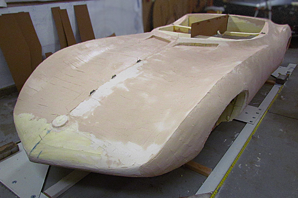
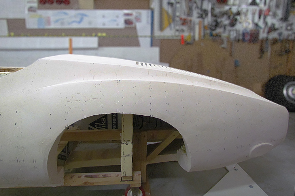
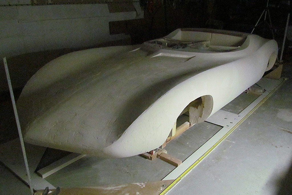
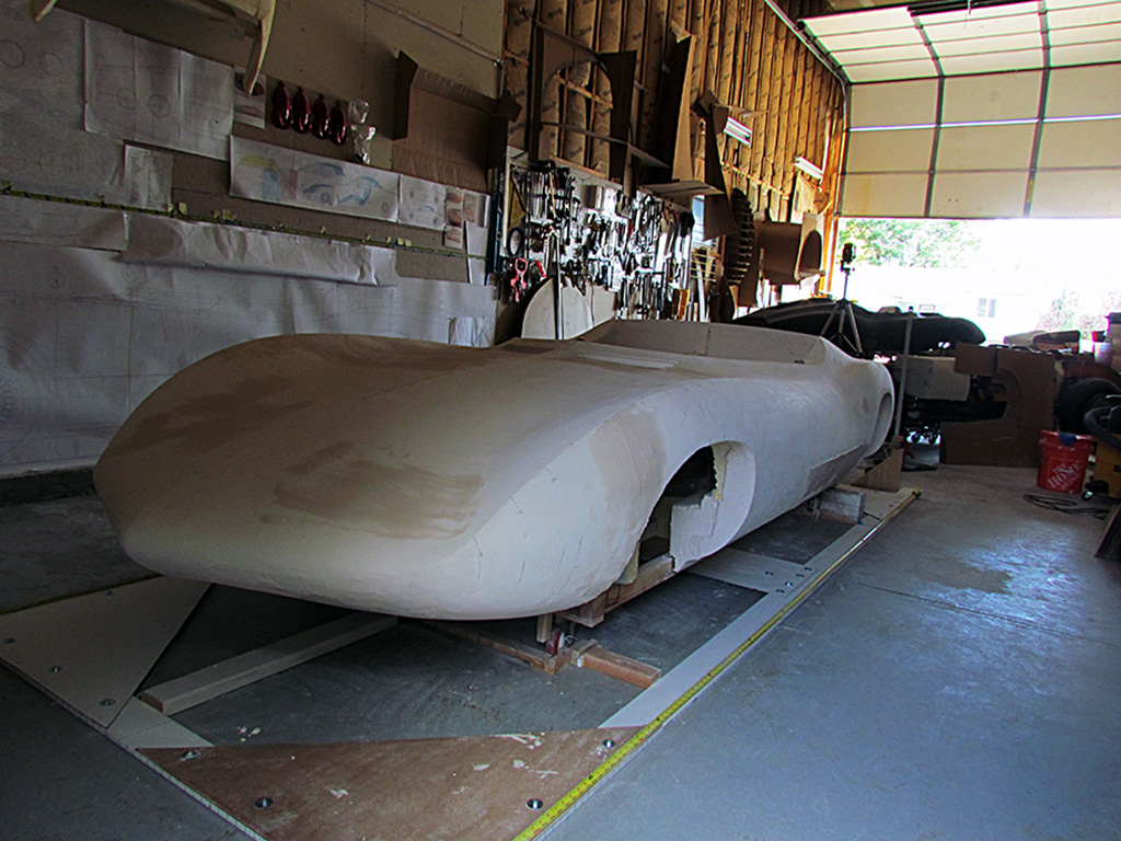
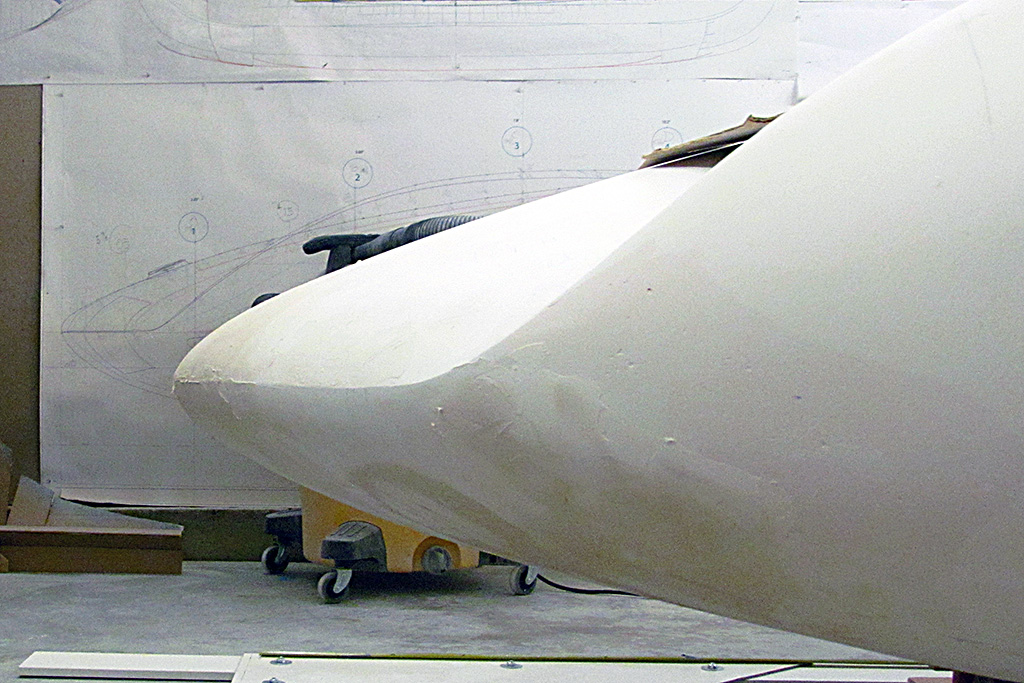
(CR) The foam body based on the 2016 lines resembled the original car, but had deeper valleys and was slimmer overall. It was closer in style to some of the racing spyders of the '50s.
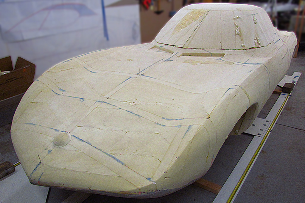
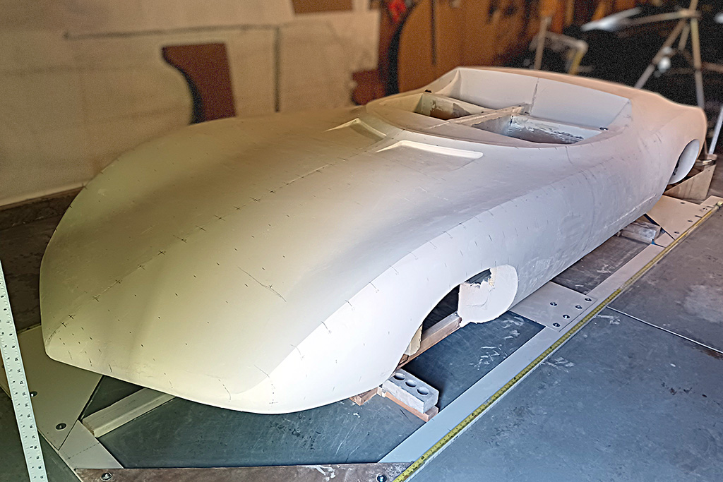
(R) Although the form looks very curvacious, it is less so in reality. A very subtle, sophisticated modeling.
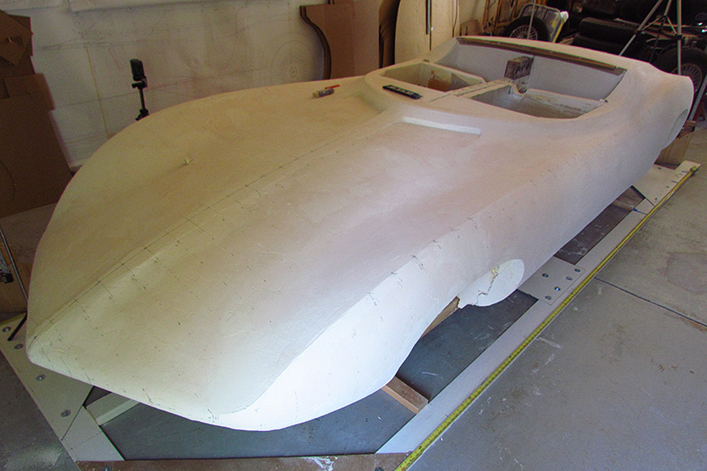
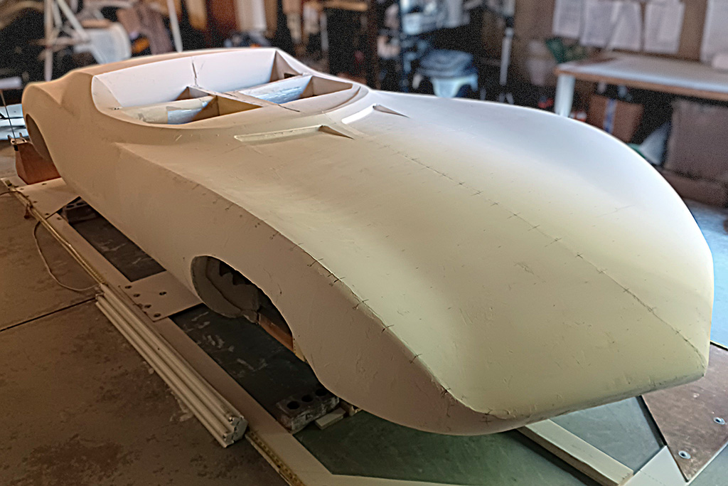
4th ROW - Walk-Around
(L) Back to the centerline contour - this shows the height difference I was getting. Ugh!
(CL) Let's do a walk-around while the latest slathering is drying...
(CR) hmmmmmm-m-m-m-m
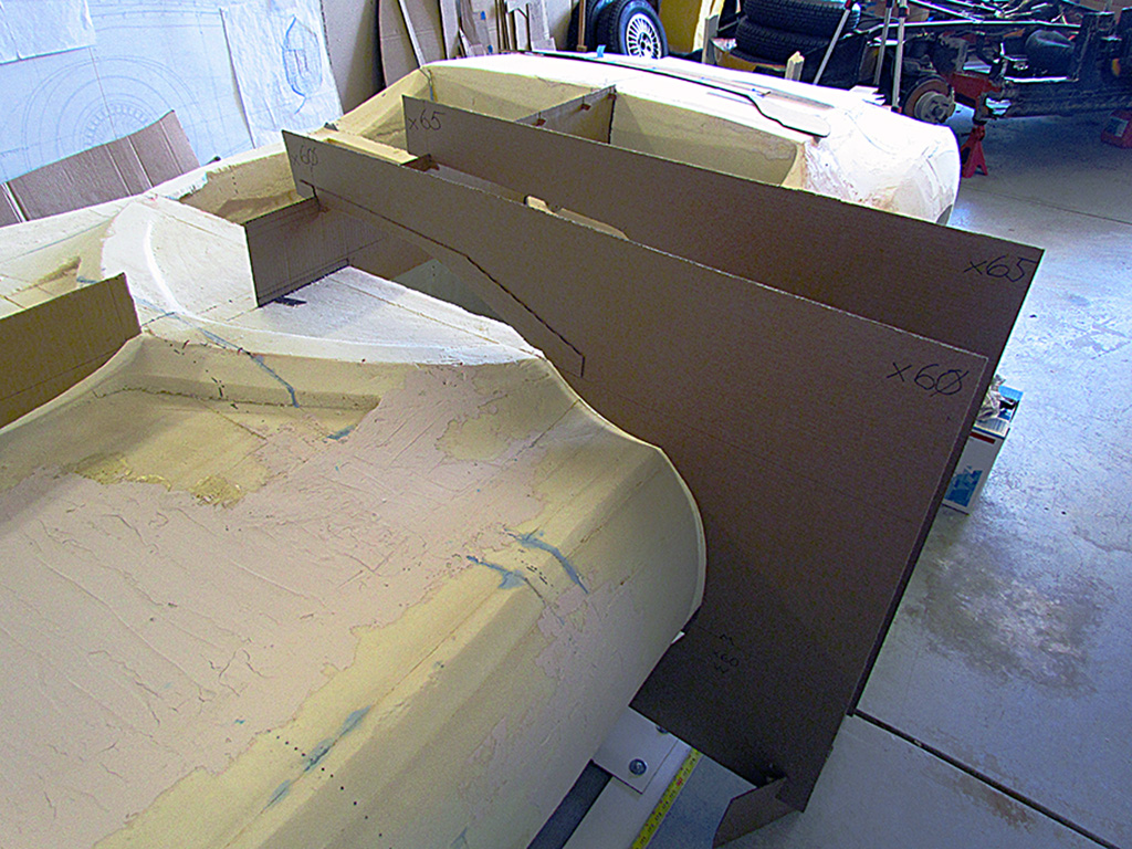
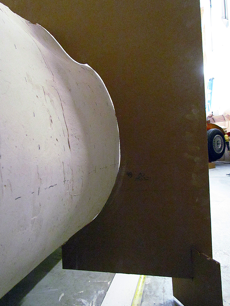
(R) I plan on cutting away 2" of foam around the Kamm tail and adding Bondo to shape the blend between the tail and surrounding body. It adheres better than the topping, which is pretty good, hard, but brittle. Topping will blend better to the Bondo, I think. The tail is a combination of Bondo, foam, and cardboard.
May-June
1st ROW - Rear Deck Contours
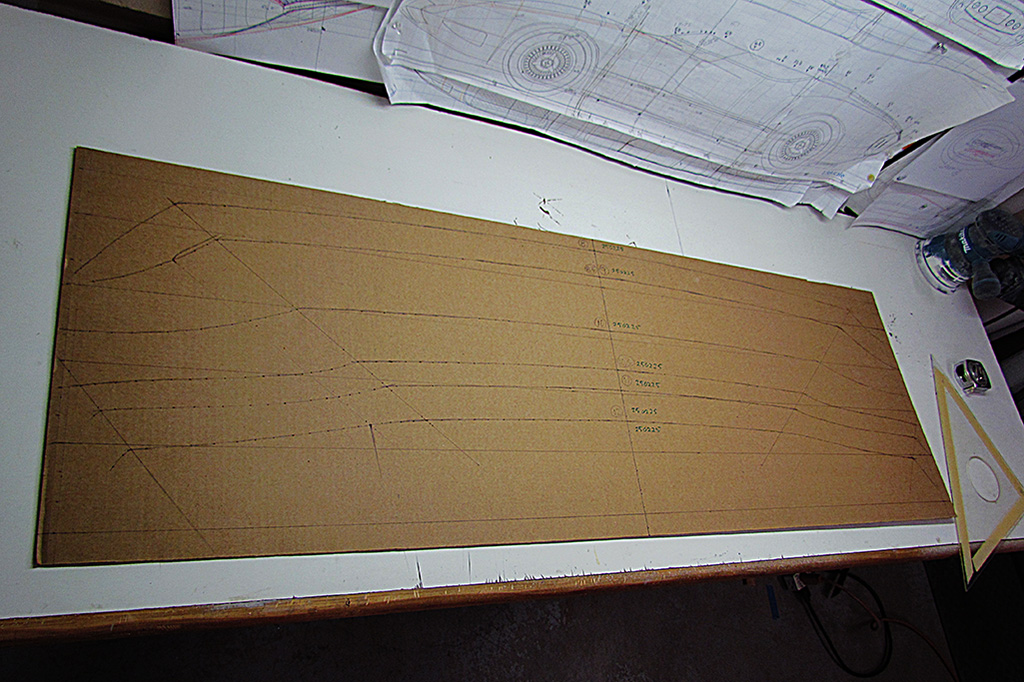
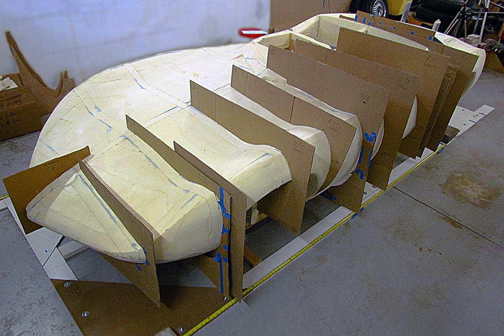
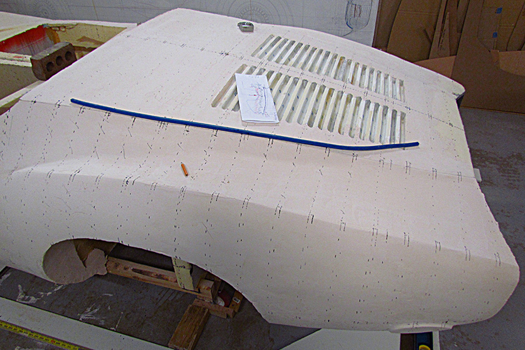
(L) A contour panel tacked out and the cut line drawn. They are made so that the left side extends to the front-rear centerline. I add the horizontal midline and the wheelbase centerline, plus where the fender and rear deck ridges should fall.
(C) here is the contour for behind the seat where the rear deck begins. All that light shining behind it means I need to add more plaster to fill the gap.
(R) At work marking off every 3 inches front-to-back plus the centerline. I marked out the rear deck and fender ridges and tried connecting the points with a large flexible curve. I found it easier to a long, thin metal rod instead.
2ndt ROW - Rear Deck Contours
(L) After sanding to my marked line, it looks pretty good! Note the yellow measuring tape on the back wall. I align my marking laser to the same position on that tape and another on the floor on the driver side.
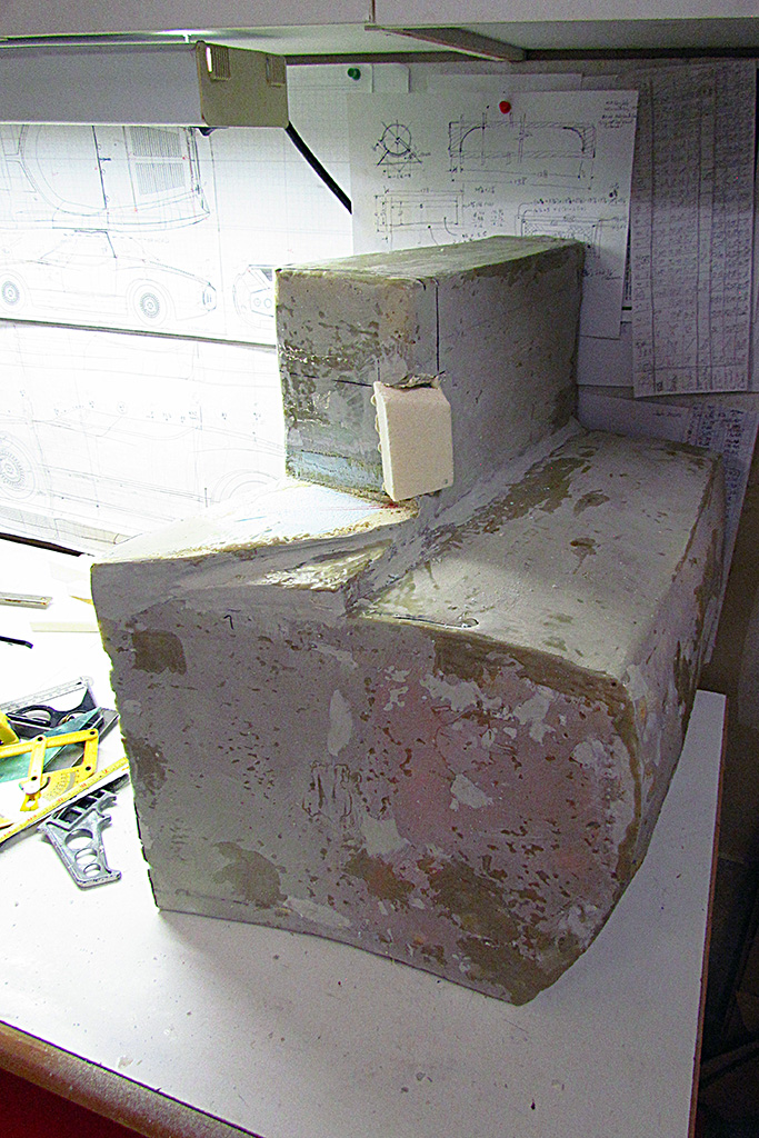
(CL) A look-down view. Note the cracks and pits in the plaster. Cracks mean I applied it too thick. Pits mean I did not smooth out the plaster enough. I learned I must surface-mix the plaster till it is smooth mud-like before applying, as well as work it on the body.
(CR) After cutting away the last 2" of foam, I saw I had cavities around the Kamm piece. I filled it with insulation foam and let it sit a couple days. I had not yet plastered under the rear pan.
(R) Top view of the foam that expanded outward around the Kamm.
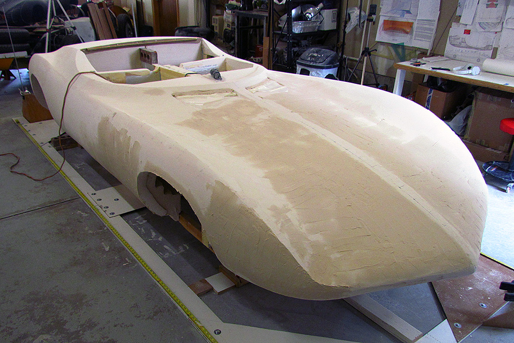
3rd ROW - Rear Deck Contours
(L) I trimmed the excess foam and began building up plaster all around the Kamm.
(CL) The plaster all built up and ready to sand down.
(CR) After the first round of sanding. Note where I sanded down to and into the underlying foam.
(R) Continuing to build up the surfaces with plaster. It goes on as a light tan and dries to a cream white.
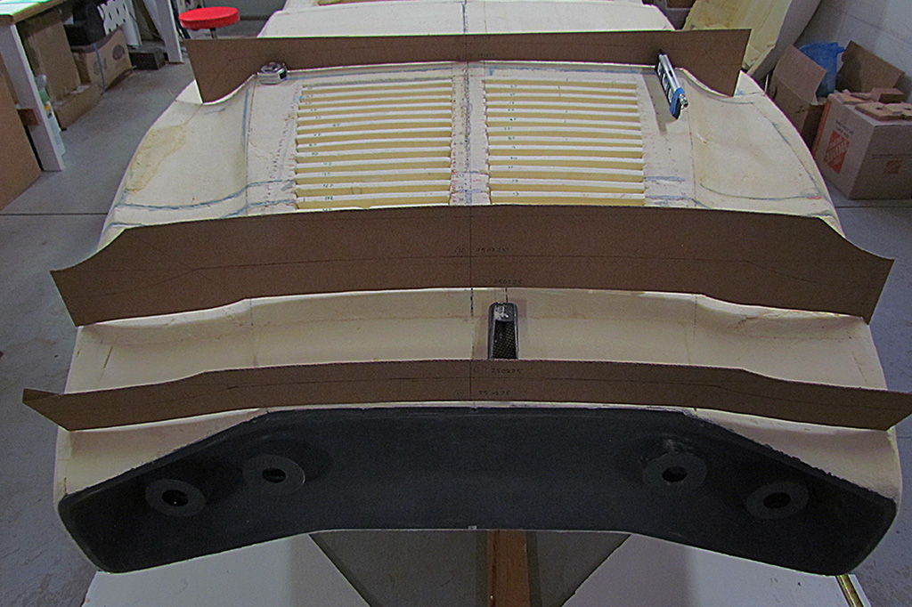
4th ROW - Rear Deck Contours
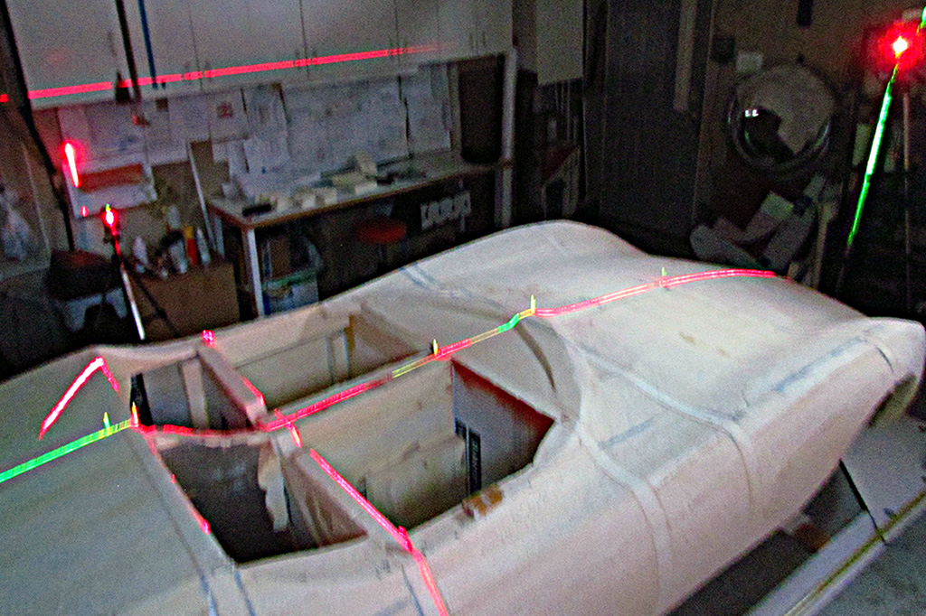
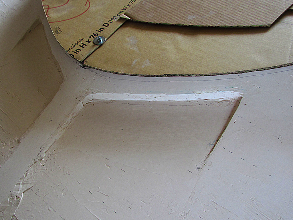
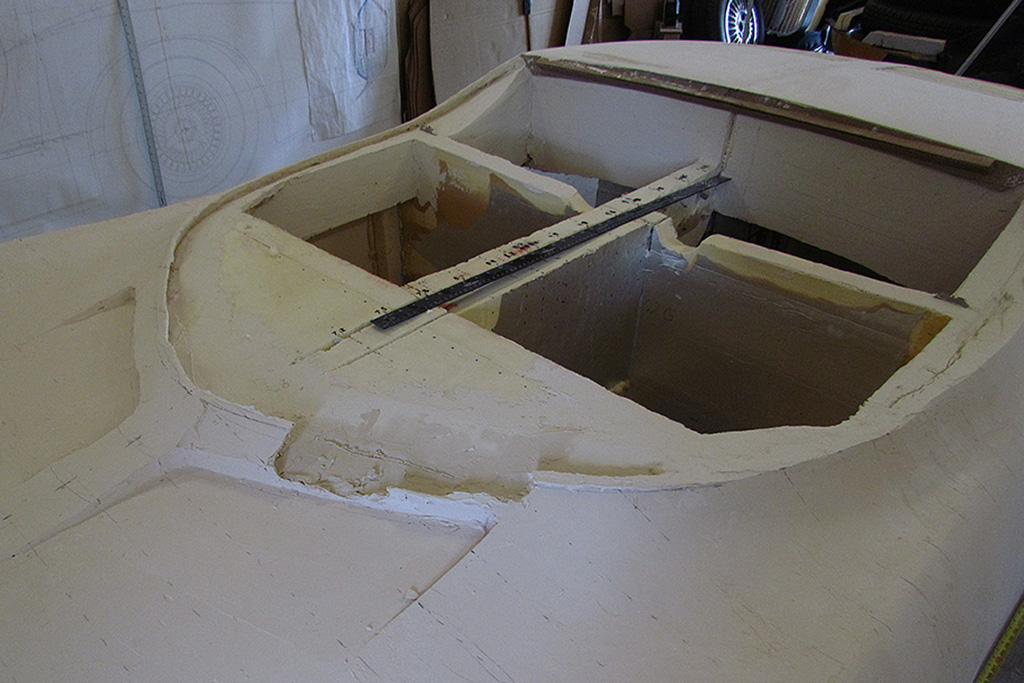
(L) I laid down my cabin contour and traced around it. Note the line below the contour. If it is correct, then my air intakes need moved forward. "If" is the operative word.
(CL) The cabin contour at the door position. It indicates the outline is wider then I had laid out.
(CR) A comparison of the nose contour. The bottom side is close. The top needs work.
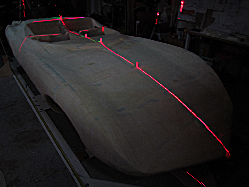
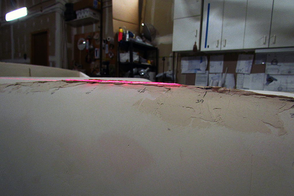
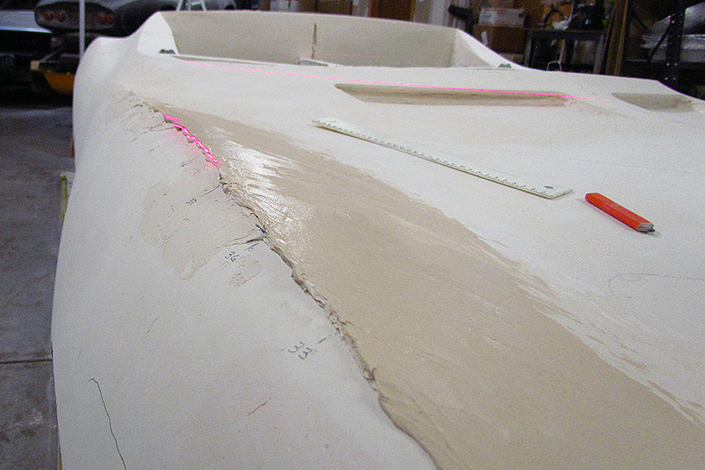
(R) Casting my horizontal laser line across the rear deck reveals that the centerline needs built up.
5th ROW - Rear Deck Contours
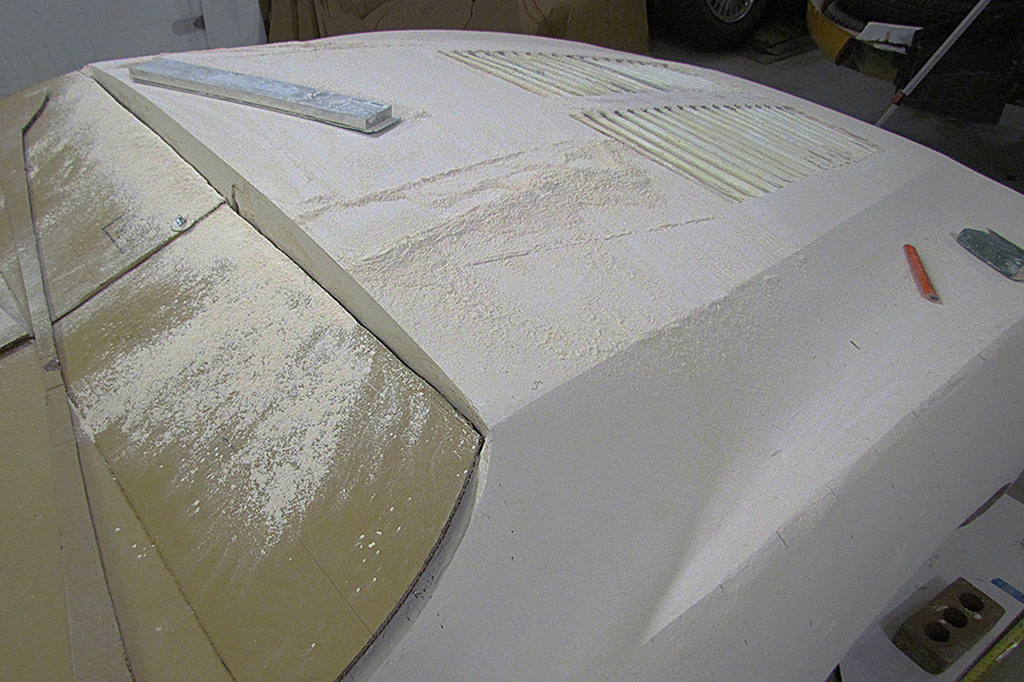
(L) It also needs smoothing out. The sanding bar is very useful over a large surface. It is easy making dust sanding plaster.
(CL) The contours traced out. They look very good for left-right symmetry. Note where the curves fall relative to the centerline 3" marks. If the lines fall below the marks, I must sand down some. If they fall above the marks, I must build up some.
(CR) After 3 or 4 iterations, they are getting much closer. Maybe only a couple more iterations to go?
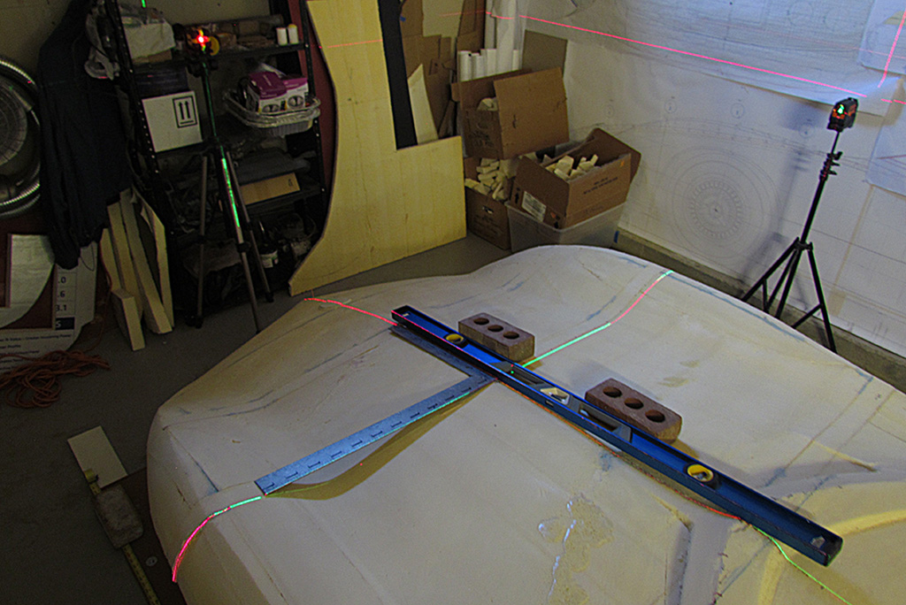
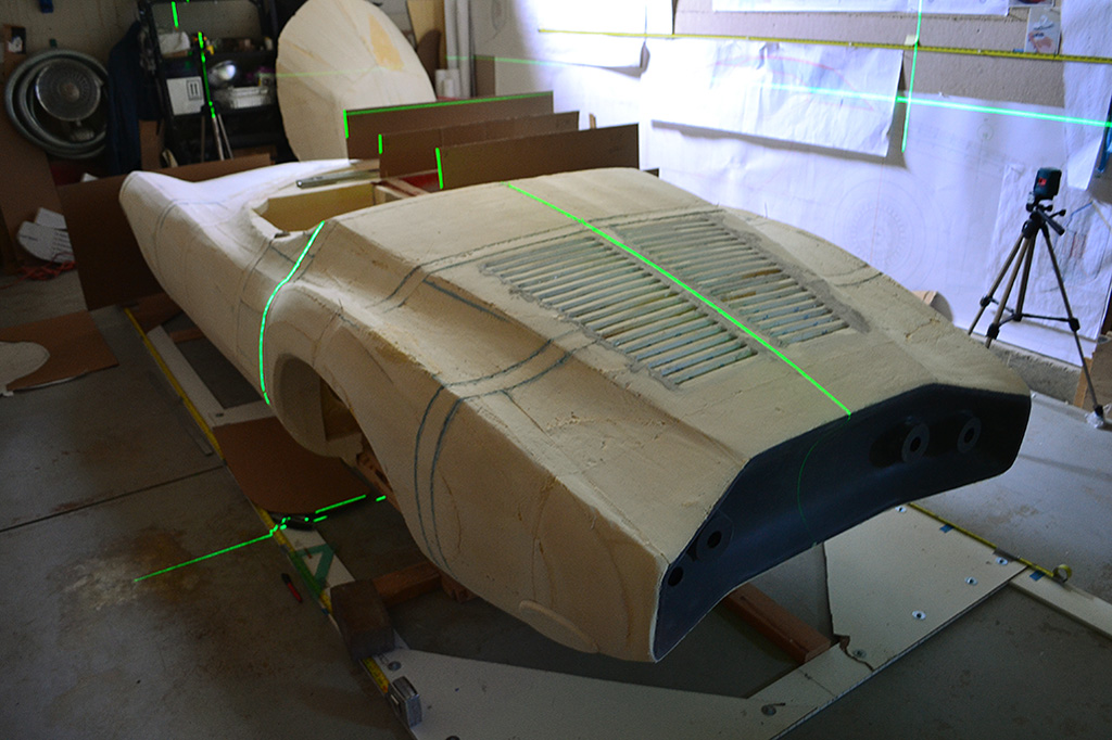
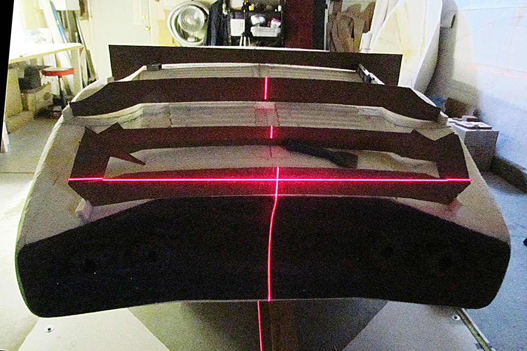
(R) The sanding bar works very quickly, so I added a front edge contour as a guide to limit oversanding. The vertical red laser line marks the centerline. Note the Chevy Jr go-kart body behind the tripod. I refer to it to see how fenders, nose, and tail were treated, and especially where the different shapes merge.
6th ROW -
(L) The tools used to mark positions for the fender ridges and cabin outline (and anything else on the top surface).
(CL) Using the horizontal laser to check symmetry left-right relative to my marked points.
(CR) This is what a typical round of slathering to build up areas looks like.
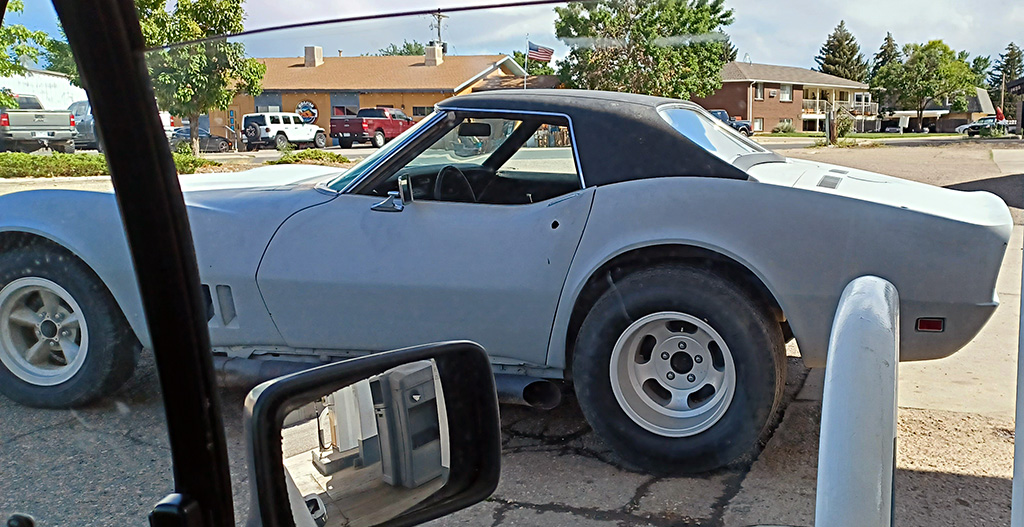
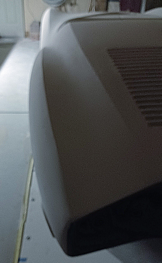
(R) This pulled in next to me at the gas station - a marvelous and original example of a removeable pop top from back in the day, circa early C3 Vette.
July-August
1st ROW - Plastering Problems
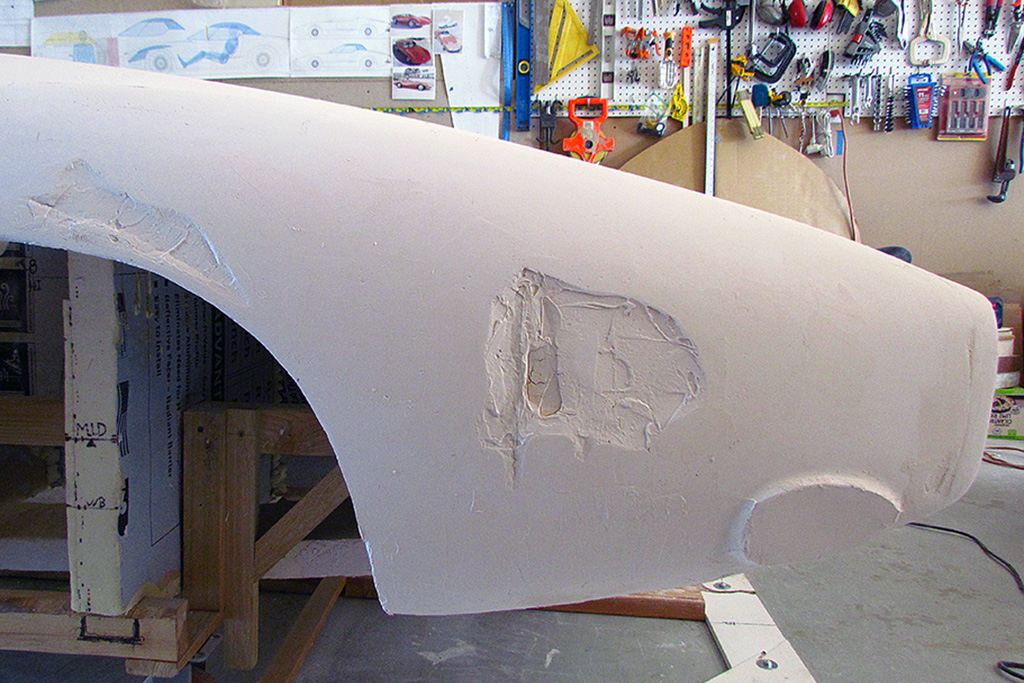
(L) I often sand down to and into the foam. I then sand down enough to have some depth of plaster, but it can make for big gouges.
(CL) I also decided to dig out the foam behind the cabin body outline. One section was so thinly plaster that it crumbled. It took over a week to build it back up.
(CR) Before shaping the front hood, I need an accurate centerline contour. I discover it needs many applications to build up.
(R) Checking the centerline. My contour guide are made to extend from the centerline, so they must just touch it when properly in place.
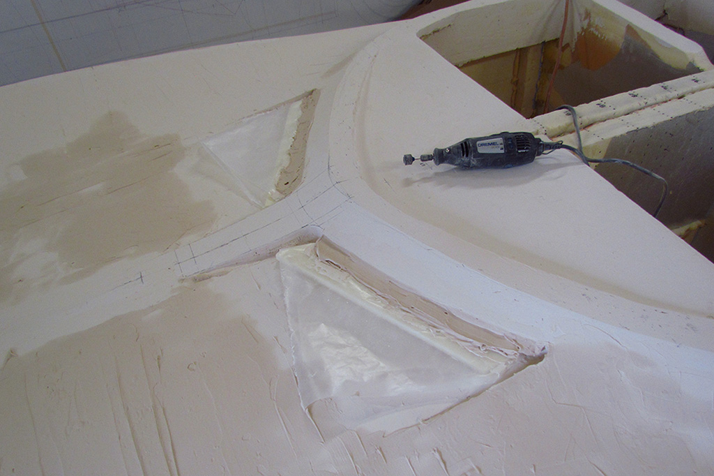
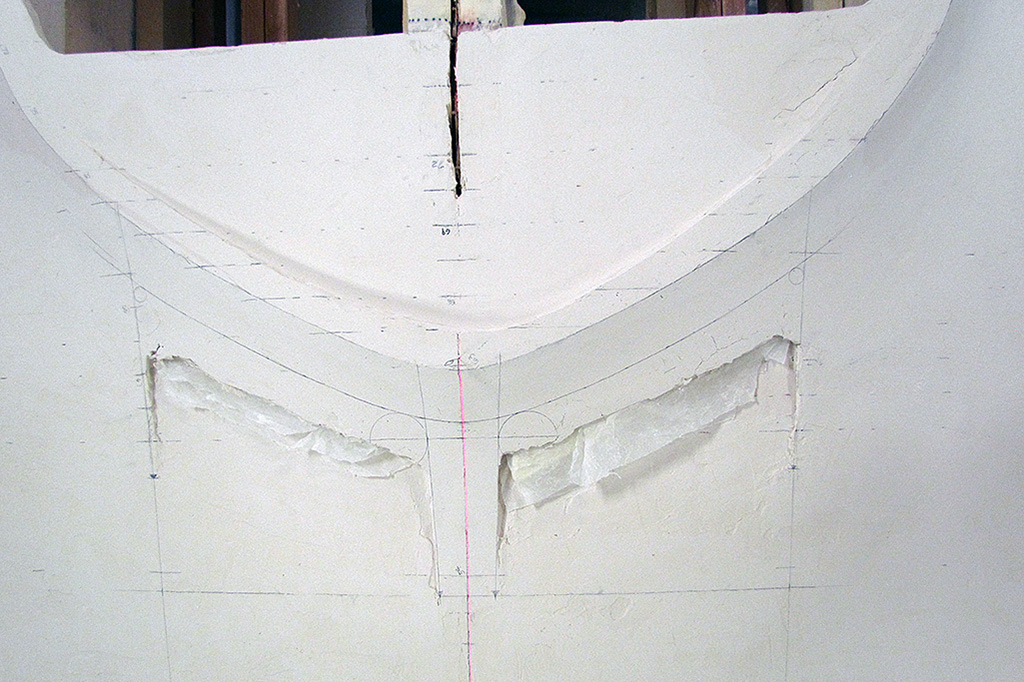
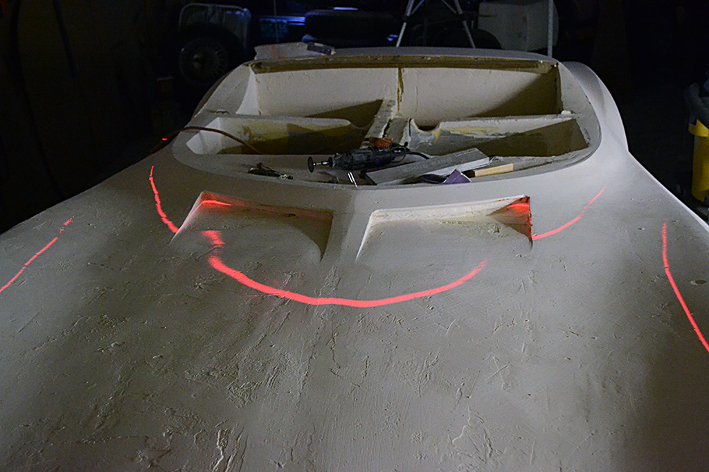
2ndt ROW - Intake Vents Construction
(L) Once it was rebuilt, I could address the correct position and shaping of the intakes in front of the cabin outline.
There is an undercut here to allow me to shape the lip and the shape a half inch in from it.
(CL) The wax paper is there while building up the plaster. It protects the block that fills the intake cavity and comes off the dried plaster fairly easily.
(CR) The shaping trick here was to make the intake lip outline be equidistant from the cabin outline all the way across.
It required some trial-and-error to decide how far from the outline it should be.
I consulted my photos and worked it out in Adobe Illustrator.
(R) Welllll... I over-extended it and must cut it back to the pencil line. The inside corner is 2-12" dia. and the outside corner is 3/4".
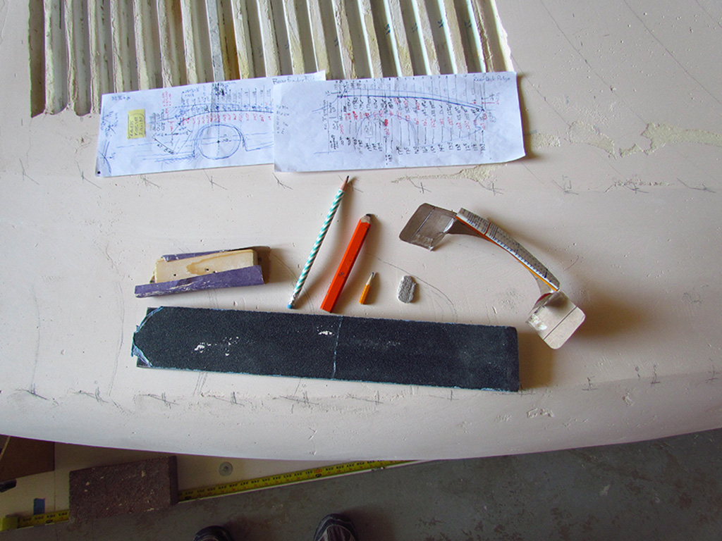
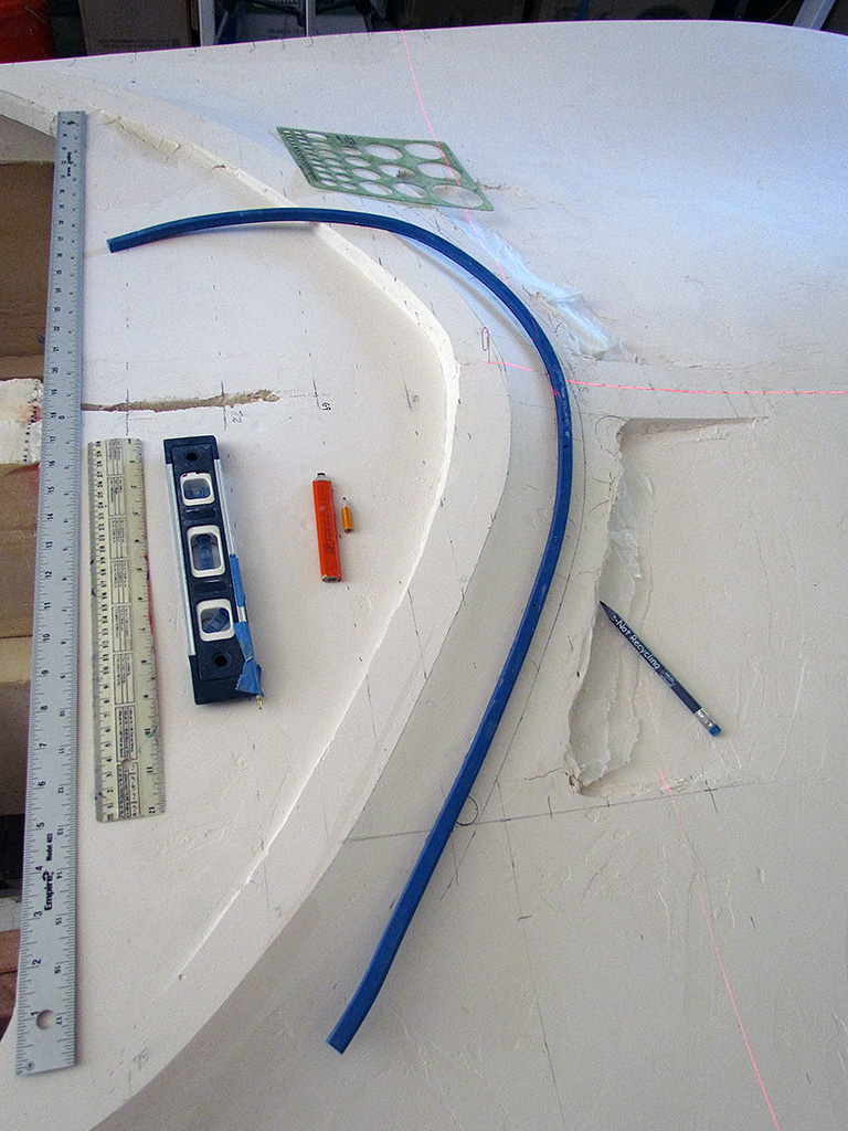
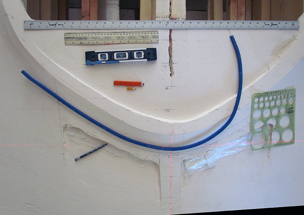
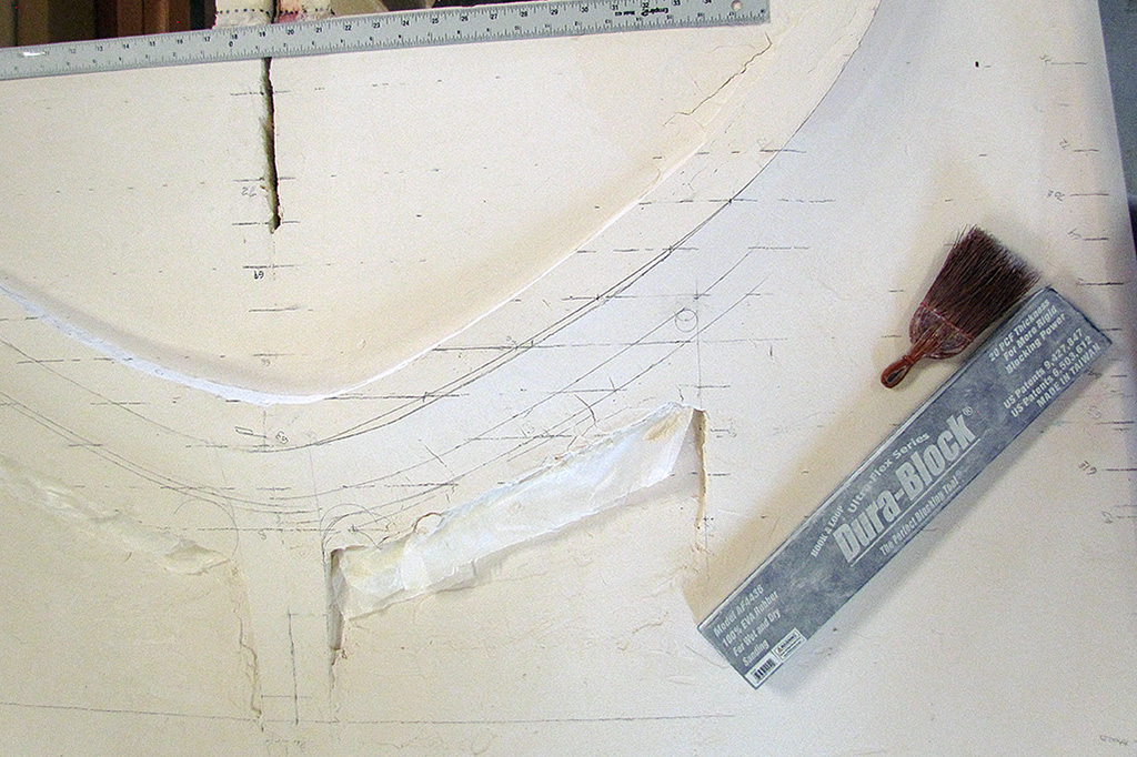
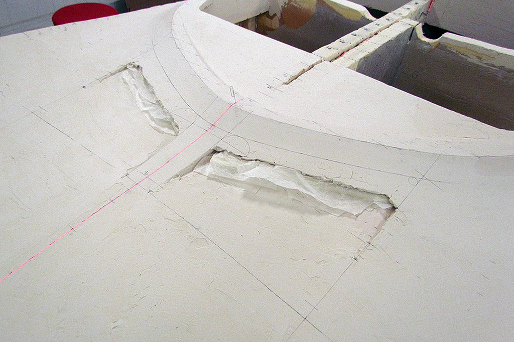
3rd ROW - Intake Vent Layout
(L) These are the tools used to layout the intake vent.
(CL) A view showing various marks from my layout trials for position and shape.
(CR) With it decided, this is where it will be.
(R) The look-down view.
4th ROW - Progress
(L) Using a sidelight, I can visually check the surfaces.
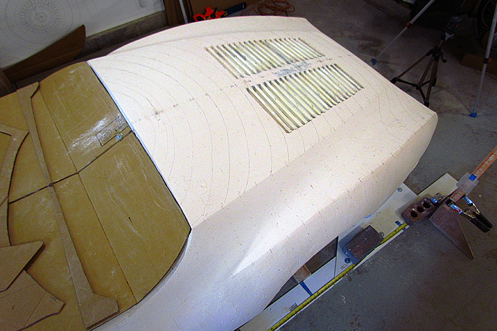
(CL) The intake vents positioned and shaped. That hood will need work. Compared to the centerline, it looks like I overplastered the hood.
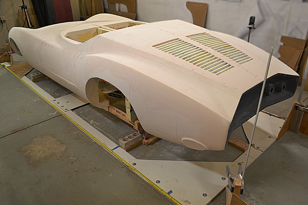
(CR) Things look pretty good from the rear.
(R) The fender ridges are looking good. And so does the wasp-waist.
5th ROW - Plaster Remixing
(L) Laser test for symmetry.
(CL) The nose area is building up well.
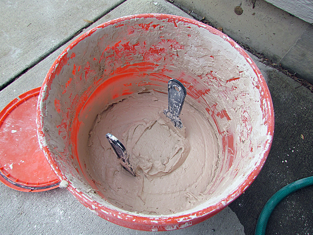
(CR) I experimented mixing up the plaster I have sanded off. 3-1/2 gallons of plaster weighs 48 lbs., about 18-1/2 lbs. is water by weight. It should evaporate during drying.
(R) I mixed in about 2 parts used plaster to 1 part water and mix it well. The consistency looks creamy smooth like the brand new plaster.
But when it dries, is leaves a rough surface. But it turned out that this is easily sanded smooth. BUT... when I left it capped for a week without using any, it molded green fuzz. Out it went. I won't mix up any more.
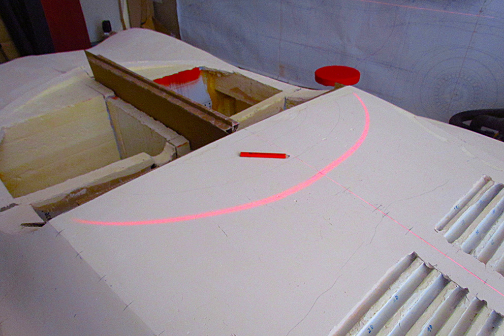
September-October

1st ROW - Shaping Rear Deck Edge
(L) Pursuing a line of exploration about the early body color. It was under a tent of apparent yellow. The image is color corrected on the wheel rim, sharpened, and then increasing saturation was applied. Using the grass as a color check, the 1st is most color correct, but the saturtion on the body looked off. My conclusion based on this photo would be the original color was an orange-red.
(CL) Progress check. Rear deck is good. Beginning to build up the door crease.
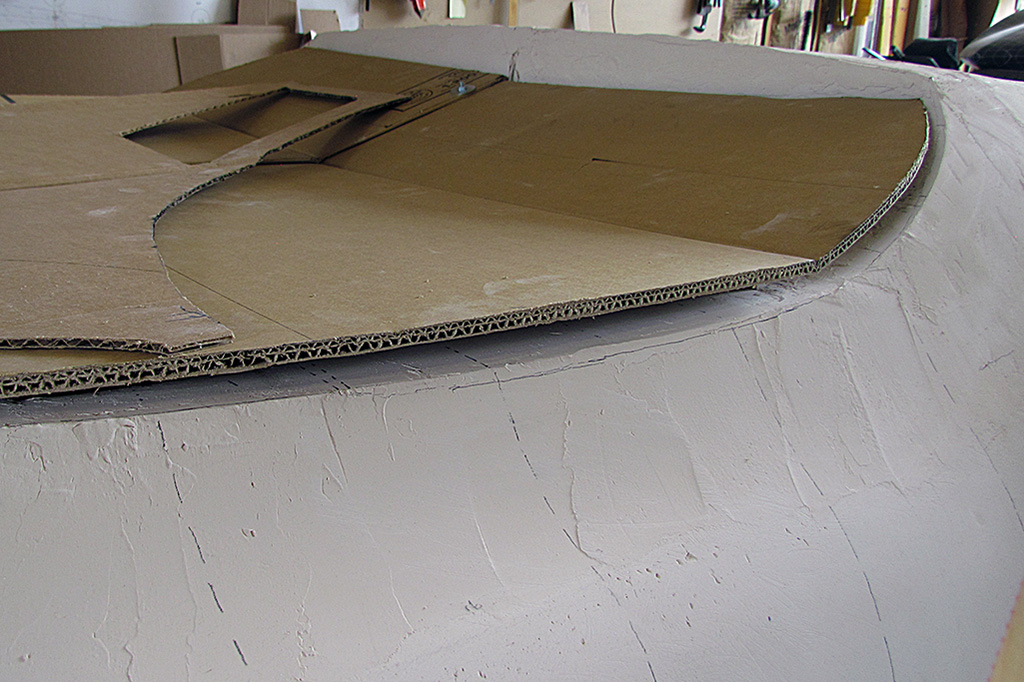
(CR) Preparing to define the rear deck front edge curvature. A template was used to draw the line.
(R) The template in position on the passenger side.
2nd ROW - Progress Check
(L) More sanding and a progress check, driver side.
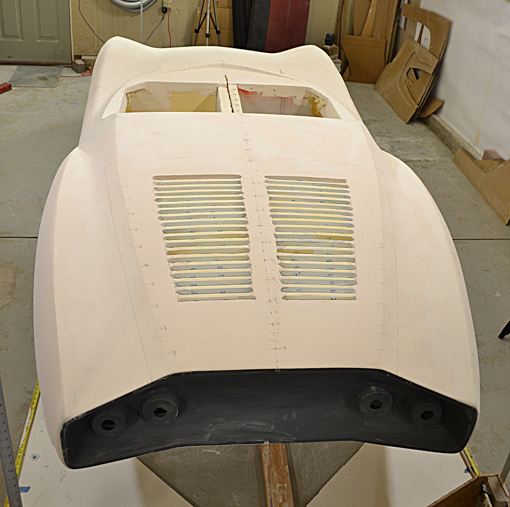
(C) Tail-on view
(R) Passenger side.
3rd ROW
(L) Front view, driver side.
(CL) Front view, passenger side.
(CR) Rear view with backlight highlight.
(R) The same, driver side.
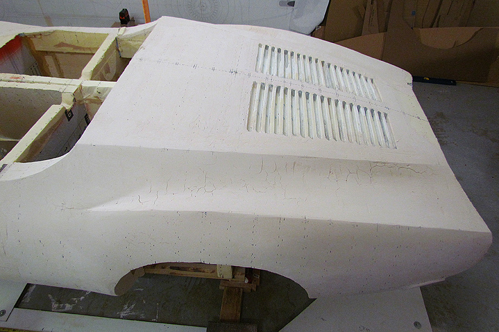
4th ROW - Building Up Louvres
(L) Inserts to create a straight edge. Made from wax paper backed by foamcore strips and tensioned with cardboard pieces.
(CL) Once the strakes between the intakes are plasterd, the rocker panels continue their build-up.
(CR) How the strakes look after two applications of plaster. Looks like more plaster will be needed.
(R) Only the driver side is being done, while I perfect my technique.
5th ROW
(L) Close-up of the strakes. I made a special sanding surface out of cardboard, and gave it a slight curvature to match the rear deck.
(CL) 1st sanding after adding two more applications of plaster. Still more will be needed.
(CR) 2nd sanding after adding still more applications. That did it! The edges of the strakes still need to be trimmed. I will do that when both sides are done.
(R) The passenger-side intakes stuffed in preparation to build up the strakes.
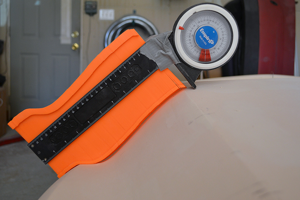
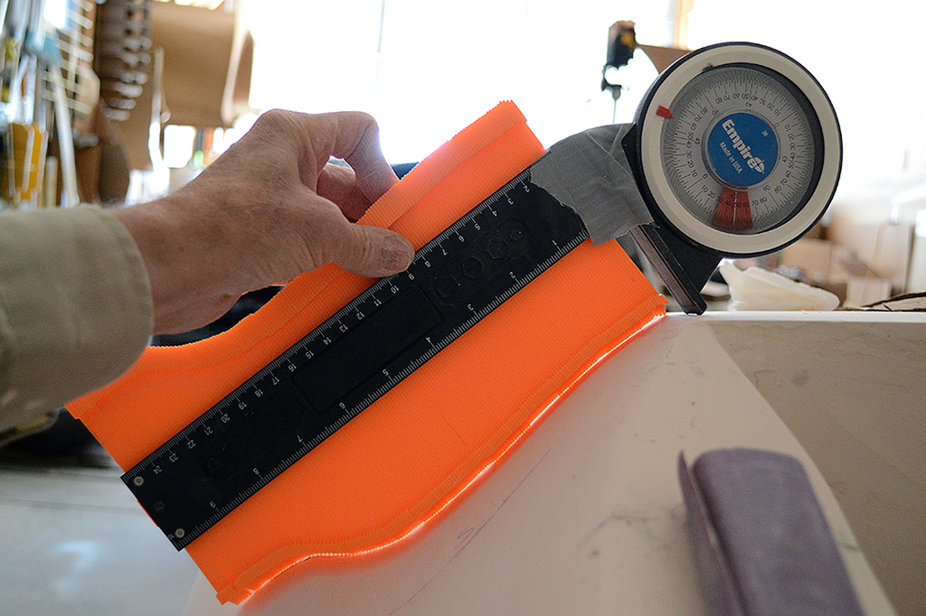
6th ROW - Contour Gauge Test
(L) Contour check, driver side. Note the angle gauge attached to the contour guide. That makes sure I compare the contour at the same angle left and right.
(R) Contour check, passenger side. Looks pretty good!
November-December


1st ROW - Fender Build-Up
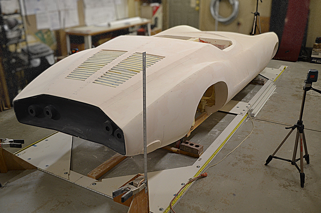
(L) The laser is used to determine the fender height at each station along the fender.
(CL) Building up the fender top along the new ridge line.
(CR) Looking forward along the fender ridge.
(R) Building up the outside of the fender to meet the fender ridge.
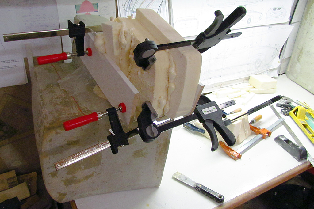
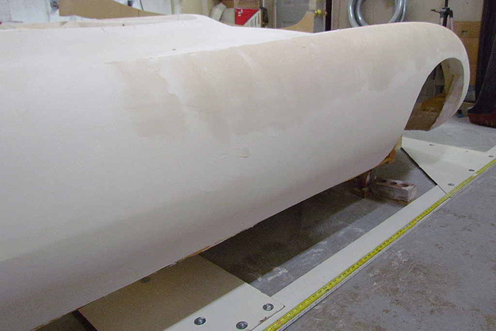
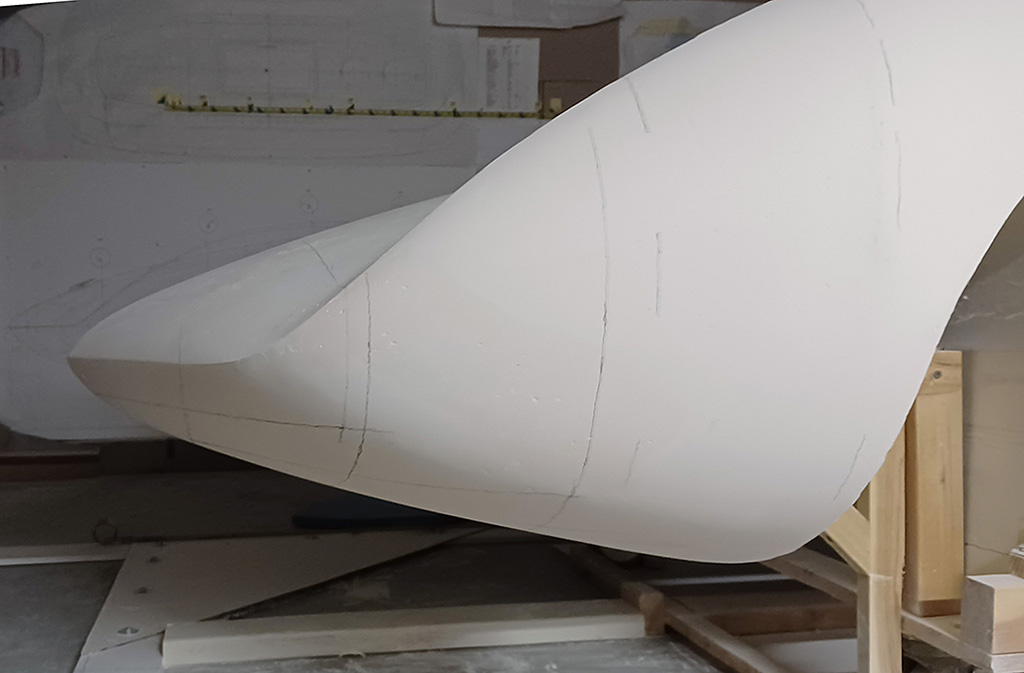
2nd ROW - Developing The Nose
(L) With best intentions, and ignoring the contour patterns, I build up the nose by eye.
(CL) All looks well looking down. It is actually about 3/4" longer at the nose than the published dimensions. I can live with that. I like it better, too.
(CR) Laser check for midline (green) and centerline (red).
(R) At this point, although I rather like the centerline profile, my contour patterns just don't fit. This is when I decide I will have to remove the Bondo to trim back the entire underpan.
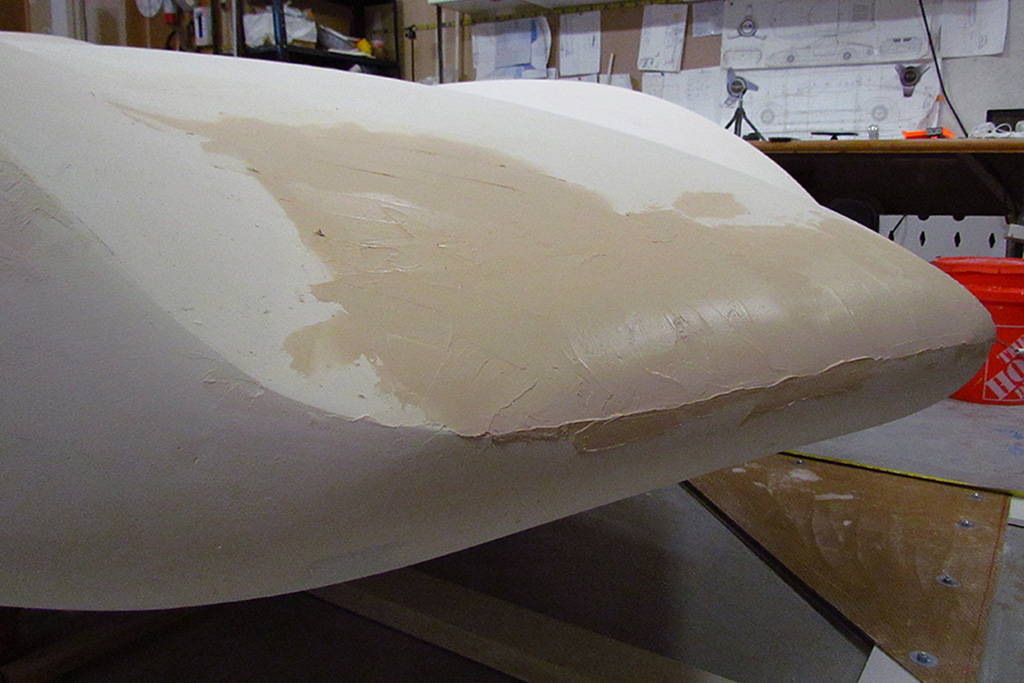
3rd ROW - The Nose Job
(L) How I established the centerline for the underpans, by carefully lining up my marks front and rear.
(CL) Most of the Bondo is chipped away. More will be removed with each slatering as I develope the curvature.
(CR) A progress review.
(R) Top view from the top rung of my 8-foot ladder. This is a perspective view - not an orthographic view.
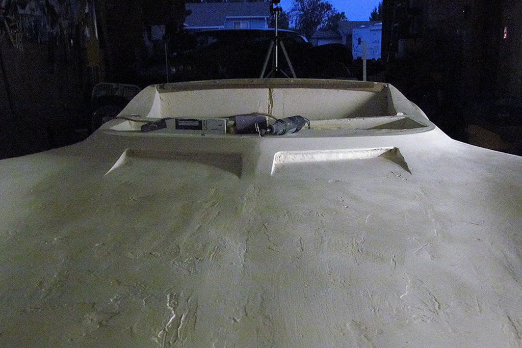
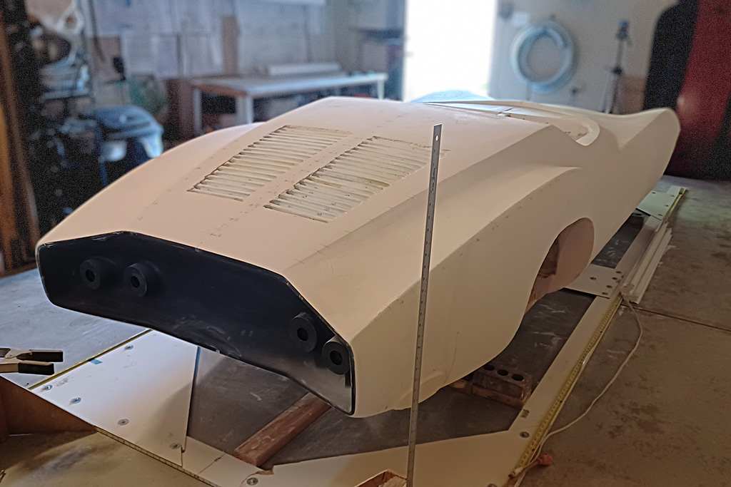
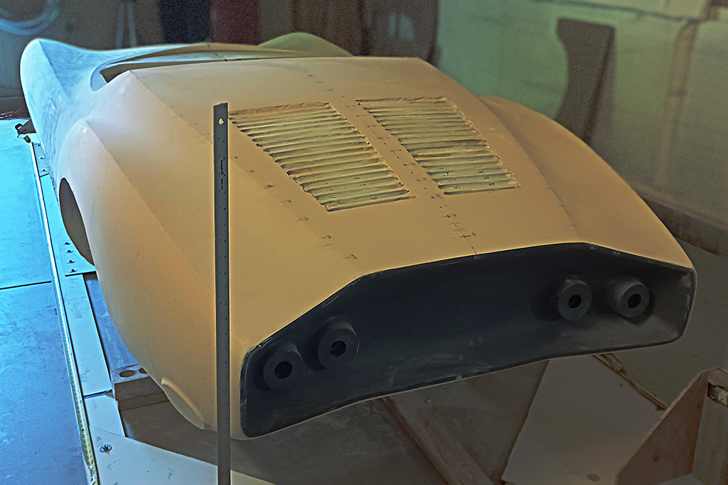
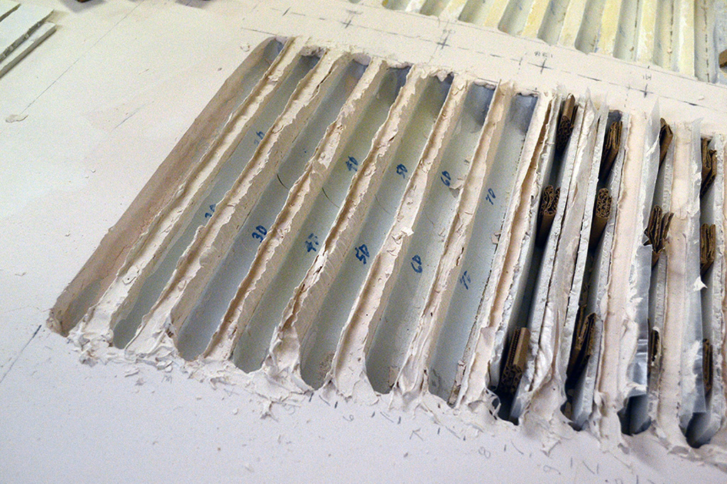
4th ROW - Shaping the Louvres
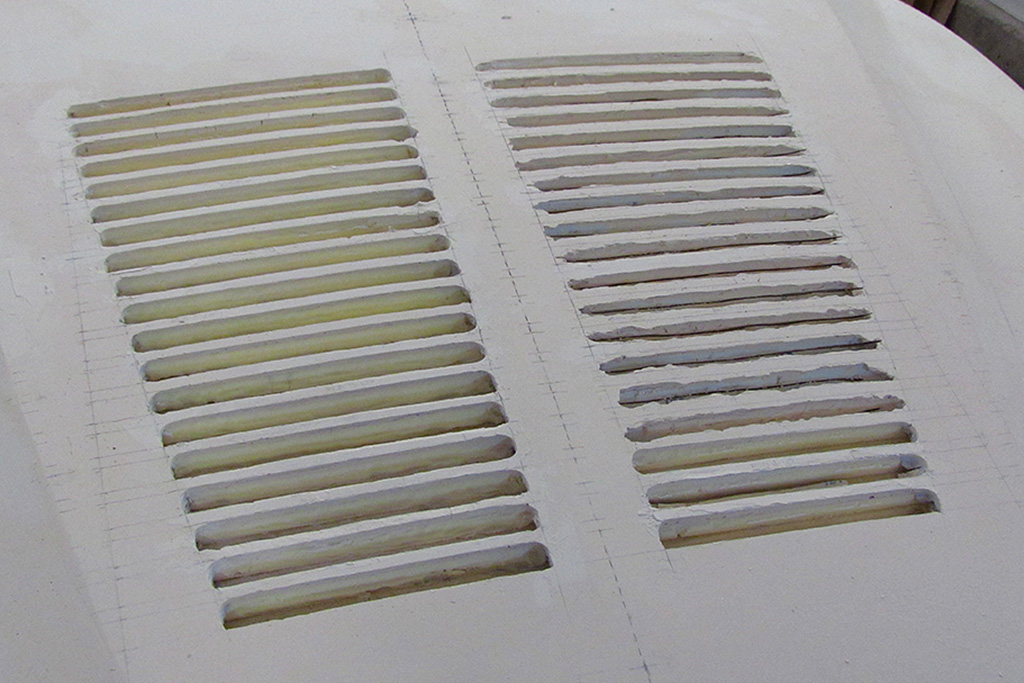
(L) Top view of louvres after building up the strakes and before trimming them down.
(CL) Close-up view.
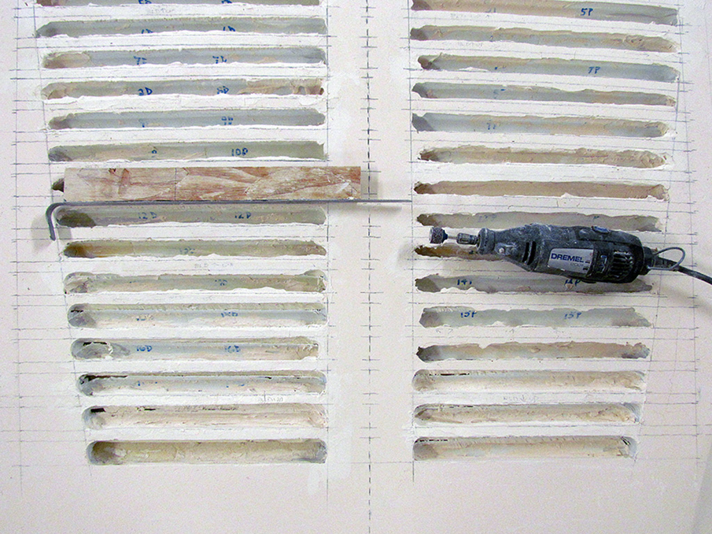
(CR) My Dremel and my metal guide. 5 on left and 3 on right have been trimmed out.
(R) The left side intakes have all been trimmed, but the bottom corners have not been done yet.
5th ROW
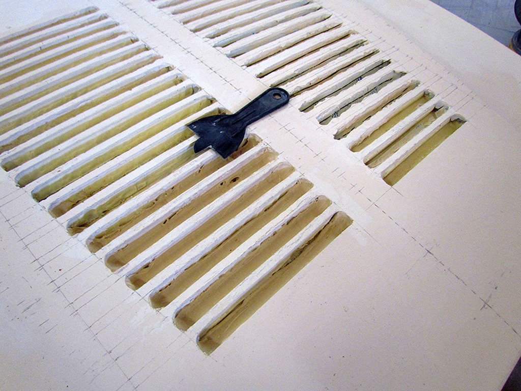
(L) My shaping tool with 8 intakes filled with plaster and shaped with the tool.
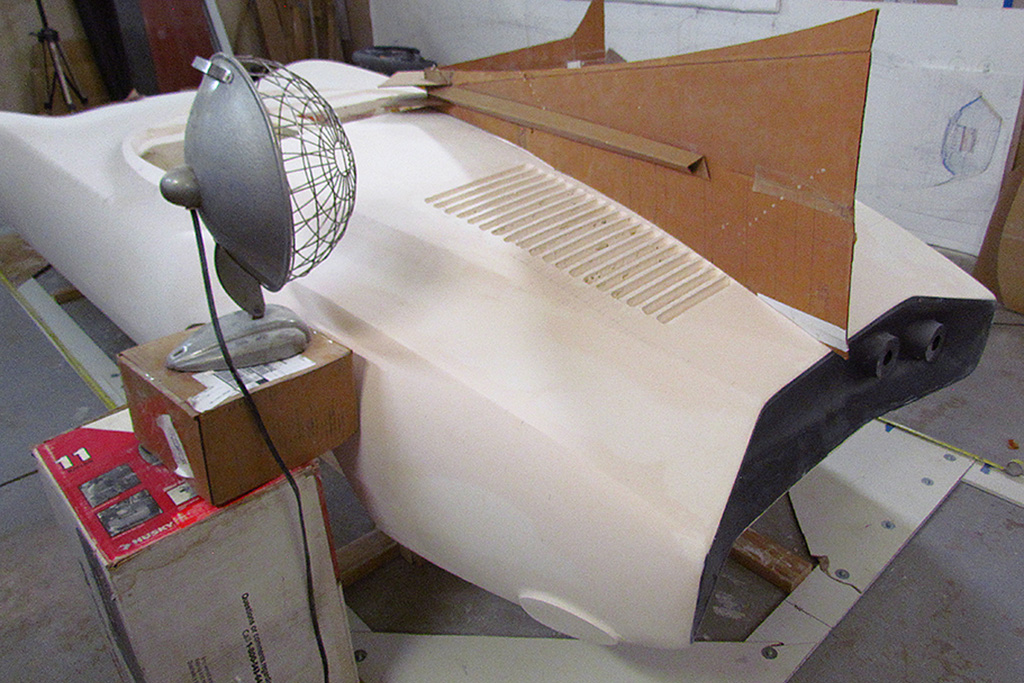
(CL) Drying with a space heater. The cardboard panel is there to bounce heat back onto the intakes.
(CR) The cardboard is also a contour guide. The contour looks good still!
(R) The right side needed A LOT of plaster to build up the strakes. This is my foam&wax paper inserts to give the intakes a straight edge. It mostly worked.
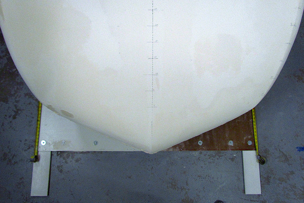
6th ROW - Nose Comparison Check
(L) 3-image comparison. The left and right images are overlaid in the middle image. The outline of the nose closely matches!
(C) The driver-side nose profile.
(R) Looking along the driver-side fender ridges.
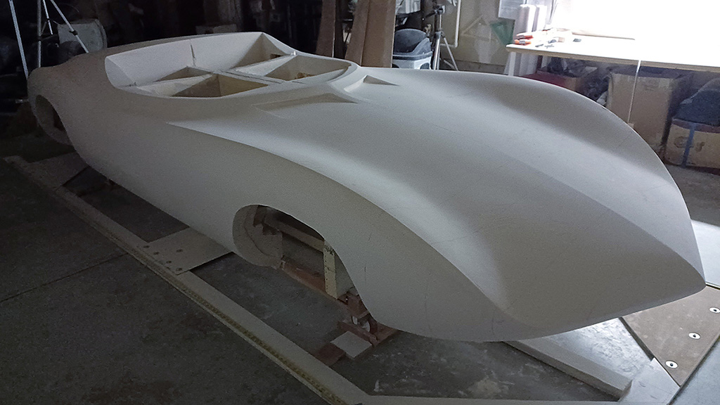
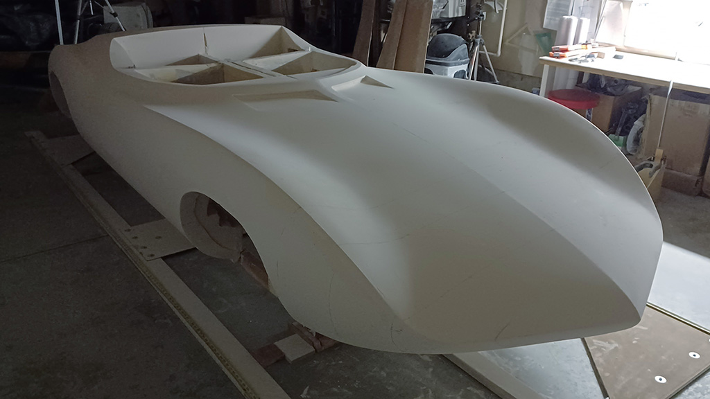
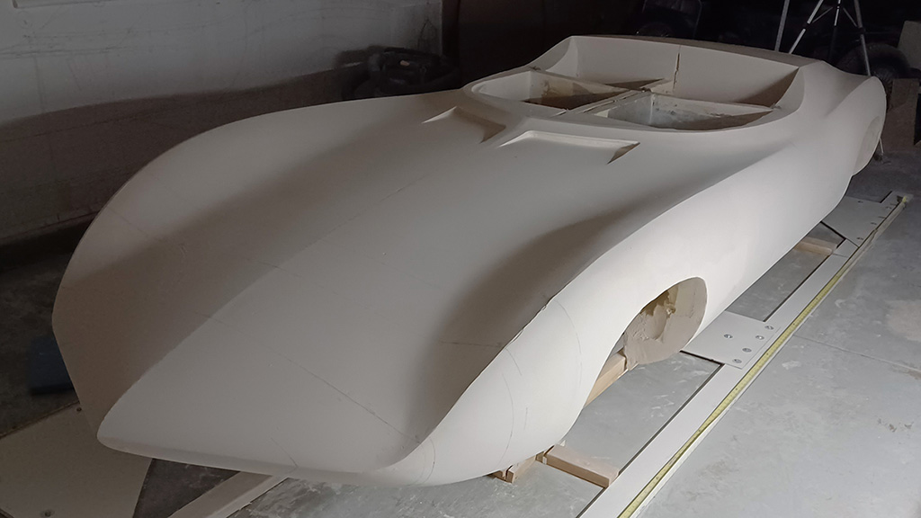
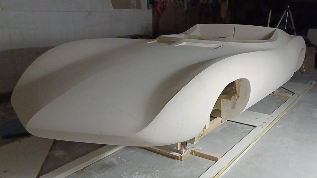
7th ROW - Final 2025 Walk-Around
(L) Passenger side, 3/4 front view
(CL) dito
(CR) driver side, 3/4 front view
(R) ditto