
Contact: Rich Kurz Page content last updated January 1, 2021
The Construction Diary
2020
JANUARY
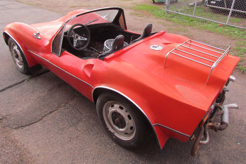
I won't be working on the chassis while I carve the model, so it's time to move the chassis to the barn and wrap it.
Before I do so, I think I can complete some items to allow me to start the engine and move it under its own power.
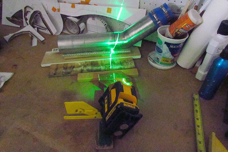
first I want to reposition the Mass Air Flow meter (MAF), which is above the hood line.
I decide to reroute it by the inner wheel well, but need a pipe with a 30 degree angle.
The best I find at the auto parts store is a 3" dia. exhaust plus adapters to go from 3" to 2-1/2" dia, but I will need to cut and weld the angle.
I spent a couple of hours and used all my drafting triangles and my laser levels to draw a good line on the pipe to cut.
Later, my good neighbor asks me if I used the old paper-around-the-pipe method. "Duuuh, nope (grrr)."
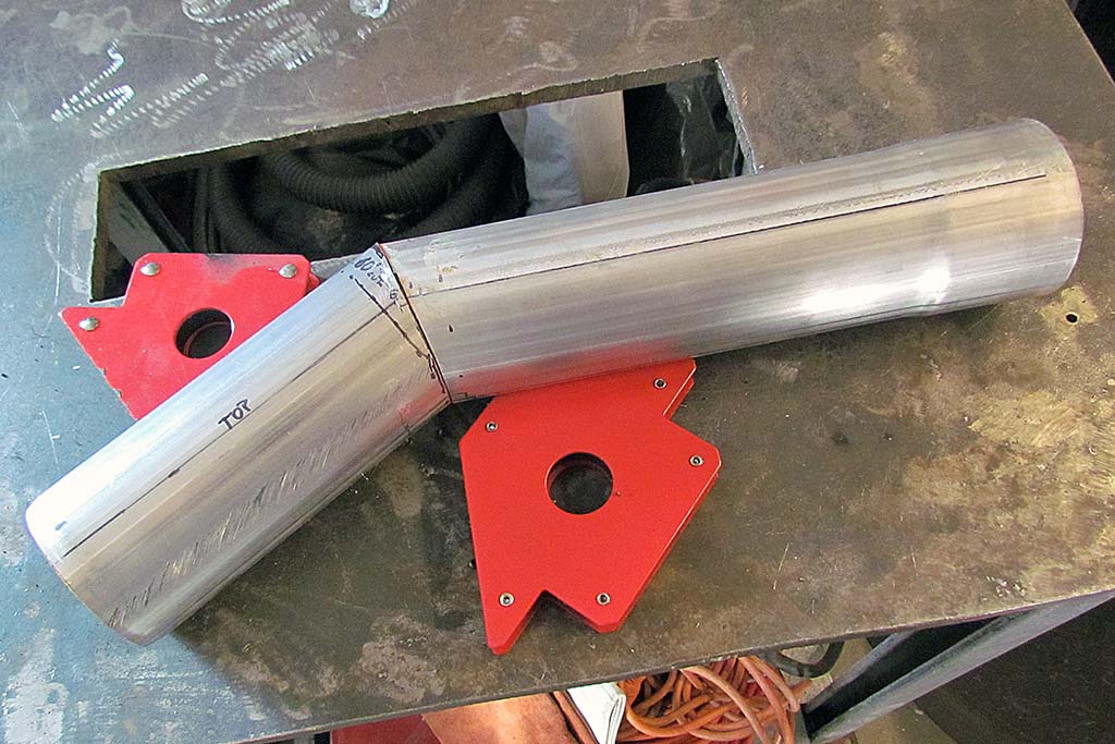
This becomes my first welding job. I succeed, but it requires a lot of grinding.
but I realize I need to make another more complicated part from the square opening of the MAF to a cone intake filter.
This is going to take too long, so I can this for now.
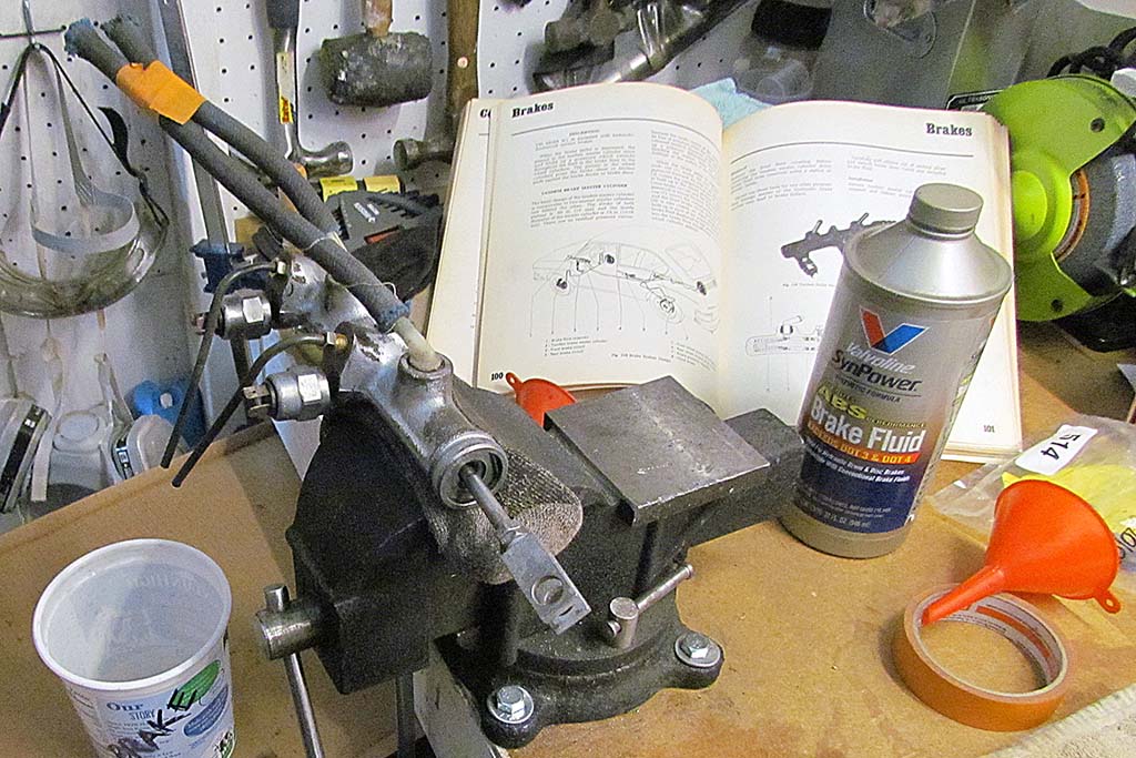
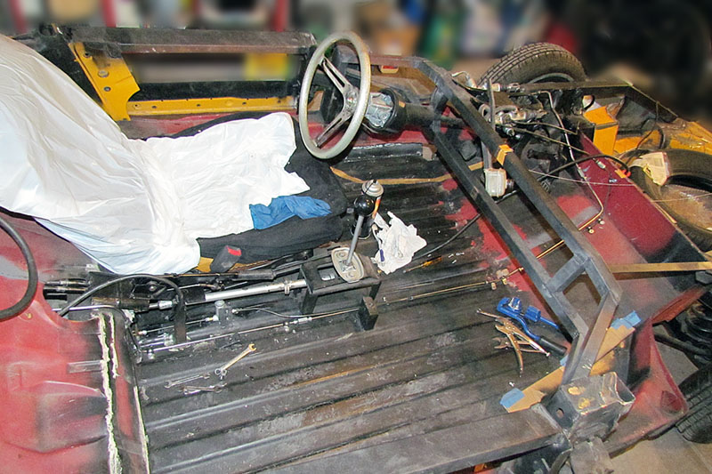
Next I want to complete the brake lines and charge the hydralic system and maybe even connect the accelerator.
I should be done within a week.
I tighten all the connections, then connect the reservoir and all is ready. My neighbor comes over to bleed the lines while I pump the pedal.
We discover we need to rotate the bleeder valve on the slave cylinder on the clutch to it is up not down. Disconnect, clean up, reconnect.
Pump a lot, and it finally works. Then do the front discs. Tighten a couple of connections, and all works well.
Begin pumping for the rear drums, and pump, and pump, and pump and all we get is a gurgle.
We disconnect the line at the proportion valve and nothing pumps out.
We disconnect the line at the connection closest to the master cylinder and nothing pumps out.
The front piston of the master is working but the rear piston isn't.
End of trial #1.
I remove the master and take it apart and discover that the seal cup has gotten pinched between the wall and the piston.
Fearing I have the wrong size cups, I search TheSamba for rebuilding a VW 412 master cylinder, manage to find and order a new rebuild kit,
get it in and layout all my pieces - old and new. There are slight diameter differences.
In the process, I discover that the 412 master is an oddball unit and extremely rare on this side of the pond since VW did not import the manual shifter versions of the 412 into the US.
What's more, they did not use the master on any other vehicle, like The Thing or the Superbeetle, which also had T4 engines.
Both the master cylinder AND the manual transmission on the 412 were unique to the car.
Well, I choose a cup that was only slightly larger than the cylinder diameter and carefully reassemble it all.
My neighbor comes over, we do the clutch and the front discs, and start on the rears. Nothing is coming out.
I looke down and see fluid coming out of the proportion valve. We tighten the connections as much as we dare and still it leaks.
End of trial #2.
Although confident we had solved all the problems, it was now the third weekend in January and I had promised to get the chassis out the first weekend.
I allowed myself no more slack and on that third weekend, pushed it out and let it roll down to the barn and spent the afternoon wrapping it in plastic.
My farming daughter got a 30'x30' piece of grain storage bag - the ones used to store grain outside and are about 100 feet long.
It is sturdy stuff and opaque black on one side and white on the other.
My big concern is keeping out the mice and voles from the chassis.
I sure hope it works. It will need to stay wrapped for 4 to 6 months.
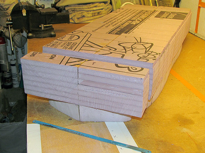
So now I can begin on the model. And lo and behold, Home Depot gets in the type of insulation foam I have been looking for.
Now to test it with epoxy and resin, glue together enough layers, and start working it to the contours.
FEBRUARY - MAY
There was of course a learning experience or two. The photo captions give a good overview of what I did and how.
I stared with a test layup, glueing contours onto sections and cutting them out, then glueing the sections together.
It sanded well enough with 100 grit sandpaper for wood. And it looked correct.
The first lesson came when I glued the top view onto the full-length piece. I was mixing Gorilla wood glue down with water at 1:1 to 1:3.
But surprise . . . the paper contour ended up longer than the piece. It expanded when soaked. I had to rub it all off and start again.
This time, I used straight 100% wood glue. That pretty well worked with only a little expansion . . . unless I kept working it to try to get it into position.
A good friend suggested I use the 1/2-inch foam sheets instead of the 2-inch thick sheets.
That would help me sanding it to shape because the lines between the layers would act as contour lines (they would be so in actuality) and help me keep the shape symmetrical left to right.
I thought that was a great idea, but stretched out my production time.
I still planned to use the contours I had created.
That would mean cutting the foam into sections, affixing the contour, trimming each section to the contour, and assembling it all together again to do the sanding.
Again, a lot of work, but I need all the help I can give myself to sand to shape quickly and accurately.
It's up-front effort for good end results.
I realized I did not need to do the lengthwise side contour down the middle. The front-to-back sections would take care of that.
But I did trace the outline of the centerline contour onto the middle cut of the foam and then glued the left and right halves back together.
I am expecting to notice it when I sand down to the black line. That's the theory.
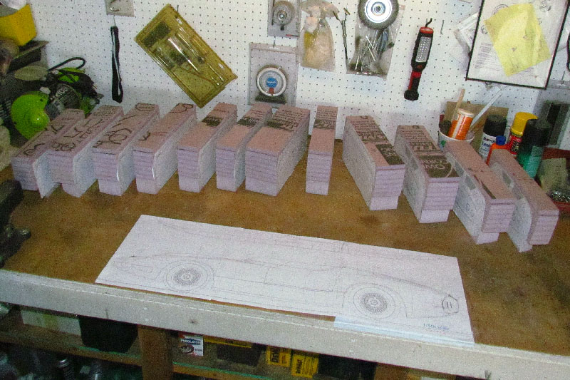
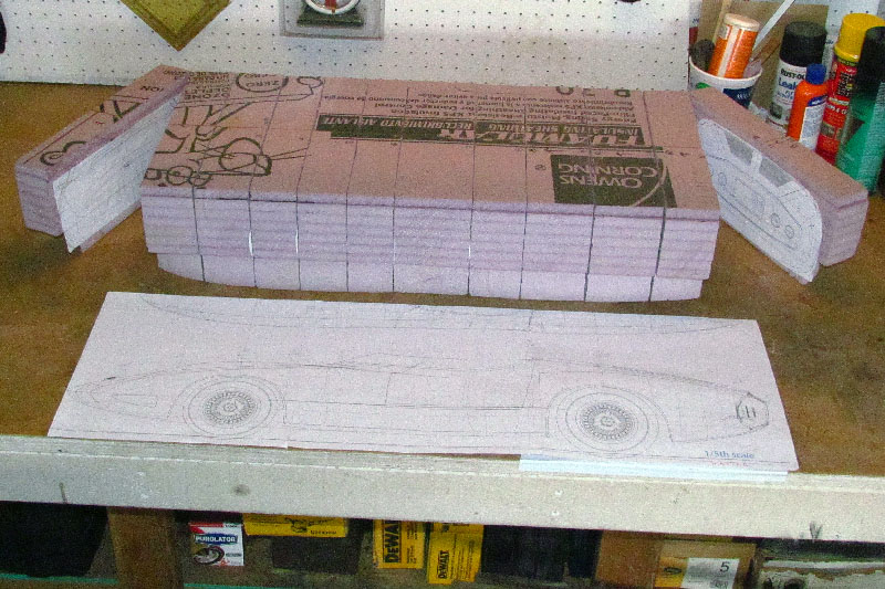
By the end of May, I have the contours glued onto the cut sections and am ready to cut out the contours with a jig saw - what is now called a scroll saw.
JUNE
At last, I can glue all the sections together.
A friend let me use his scroll saw and band saw to cut out the contour sections.
It took only over an hour, with gabbing.
Then I cut out four chipboard spacers, taking the chipboard from cereal boxes.
My length measurement said I only needed that much.
The spacers were added about evenly spaced front to back.
Again, I used wood glue, straight out of the bottle.
When dry, I experimented with a dremel tool plus cylindrical sanding pad.
Even on low speed, it was too aggressive and would catch and dig a divot.
The mini-wirebrush was better and controllable, but I think hand sanding will be best.
I use a course grade of wood sanding paper for the rough removal, and 100 grade for sanding to final shape.
Finer than that seems unnecessary - a lot of work for little progress.
I will first carve out the wheel wells and the passenger compartment before doing the body.
I am considering also doing the Kamm cove.
Note that I cut out the recess area.
I decided to build it up with clay rather than try to carve it out and finish it in clay.
JULY
Progress slowed considerably in July.
I determined I needed to create contours in the x-y-z axes before carving any futher.
But I was distracted by other life events and made slow progress.
AUGUST
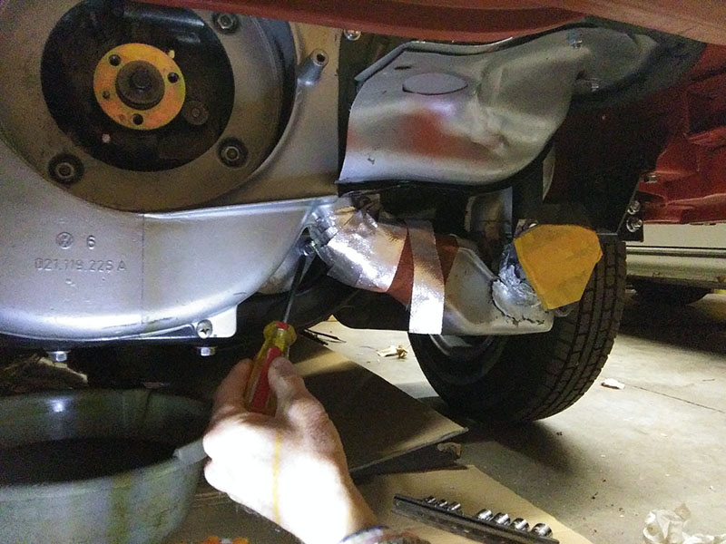
Then I realized since the weather is warm, I could have the garage bay back and work on the chassis, and hopefully finish the brakes and get it running.
I reconnected the brakes with the new connectors I had earlier bought.
My neighbor came over to bleed them, but once again I had leaks.
I tightened everything as tight as I dared and we began again, and they stayed dry! A small victory!
But after repeated bleedings, the brake pedal would go to the floor with a spongey feel.
With the front lines blocked off, the pedal quickly went hard. The rear brakes were fine!
But we could not get the front ones to work.
After much noodling, we decided to replace the master cylinder with one from a Super Beetle with a larger cylinder bore: 20.6 mm versus 19.6 mm.
I await the part.
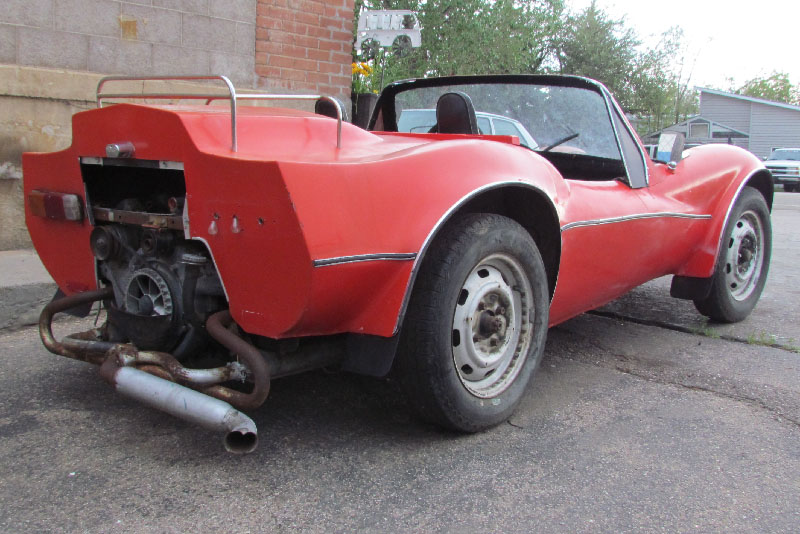
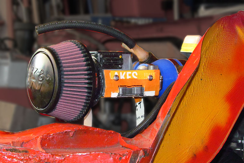
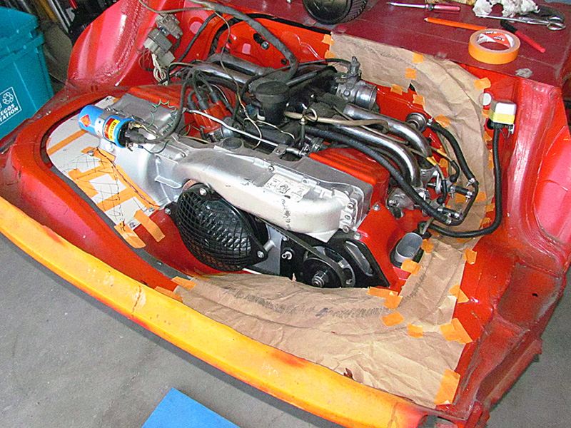
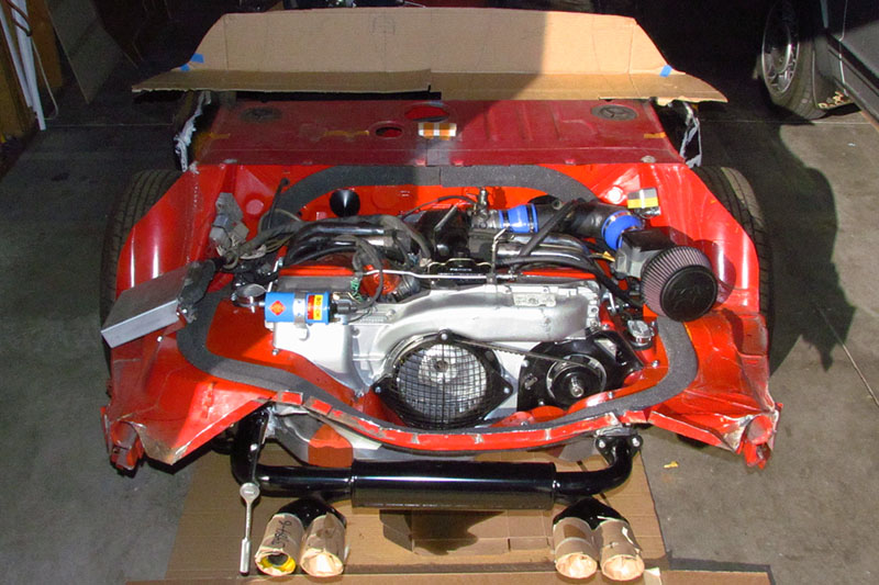
I turned next to the engine and to fabbing a new pipe from the throttle valve to the fuel injection air flow meter (mass air flow sensor meter 0 280 200 018).
I started with a 3" dia. tail pipe and cut two bends to make a 90 degree turn in the engine compartment.
That required me learning to weld, which I have now begun to do.
Then I needed an adapter from a high-flow cone air filter to the meter.
You see, although the outflow goes out a round collar, the inflow facing the filter is a square opening 1-5/8" per side.
I create a plate with a 1-5/8" cutout that I can weld a 3" dia. collar to for the filter.
Since I cannot weld well enough, I use RTV gasket material to seal the pinholes in my welds.
I then spray the entire pipe and adapter with rubberized gutter spray to further seal and to look nicer.
Oh yah. . . I also had to weld a plumbing fitting to the pit for a hose that comes from somewhere and serves some purpose.
On to the next detail.
SEPTEMBER
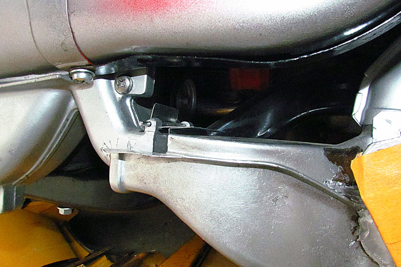
. . . which is, to make a mounting bracket for the MAF.
I created one pattern that would have attached to the inside of the wheel well - nicely out of the way.
But upon reflection I realized the MAF and pipe and filter need to be mounted to the engine, because the engine rocks in operation.
So I created a pattern with two legs that rest on the engine cooling tin.
This led immediately to the next detail - filling in the gap between the cooling tin and the engine well cutout.
This gap is typically filled with a foam gasket, and because the engine rocks, it has to have a gap of maybe 1/2" to 3/4".
But the cooling tin I have is for a '76 bus and the engine well cutout is from a 412. . . and they do not match!!!
WHY - I don't know!! It makes no sense to me! But it is what it is.
On the driver's side I have to replace the entire panel, making it uniformly flat between the well cutout and the engine.
With that done, I tape down brown packing paper to the entire passenger side and trace the edge of the cooling tin and the edge of the engine well cutout.
I then use sprayment to glue it to a large piece of chipboard I have taped together.
Then I cut it out to overlap the cooling tin by 1" to 2", and to be 5/8" away from the edge of the engine well cutout.
Back to the engine it gets taped down and trimmed and adjusted as needed.
Actually it needed very little adjustment.
And NOW I can determine where the MAF bracket legs will attach. All I have to do it cut it out of sheet metal and bend to fit.
Oh, and drill attachment screw holes and tack weld nuts on the back for the screws, and of course, to paint it. . . Almost done?!
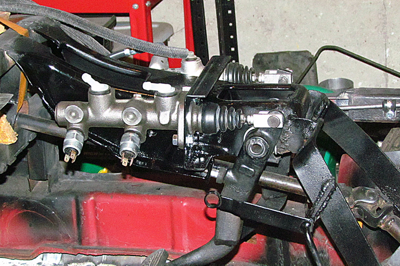
In the meantime, the master cylinder arrived and I switch over to that because it is more important, all the more so since it might not solve my brake problem.
Sizewise it matches the old 412 master cylinder, EXCEPT that it is made to mount to the firewall and be actuated by floor-mounted pedals.
The 412 had suspended pedals mounted behind the instrument gauges.
The collar for the mounting acrews sticks out such that I need to cut a notch into the pedal mounting assembly so it centers on the existing plunger.
That done, I create another pattern of the mounting surface of the cylinder and another pattern for a mounting plate to be welded to the pedal assemply on its top and side.
I used a cutting disk, then a grinding disk, and then a Dremel cutting disk and sanding wheel to carefully cut out the large hole for the end of the master cylinder to fit thru.
The rest was much easier, only it did not reach the side of the pedal assembly.
I added a piece, but even then, it just touched at one point.
I cleaned off the powder coating where I would weld, and welded the mounting plate in place and did a tack weld on the side of the assembly.
It seems pretty sturdy. And I did it all my myself without the help of my neighbor!
BUT. . . I then discovered that I could not remove the master cylinder to finish welding and painting the bracket.
That required some acrobatic careful cutting away of the side of the pedal assembly - with the cylinder still in place -
and chiseling a larger gap in the notch so the cylinder could be rotated and slipped back out from the plunder.
I succeeded without damaging the cylinder.
I quickly spayed rust protection on it and aired out the garage. Then repeat with gloss black paint before mounting it all together. Whew!
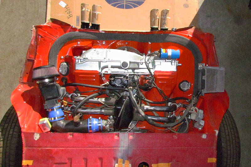
OCTOBER-NOVEMBER
First off, I moved to another garage. It allows me to work more out there.
So . . . back to the engine.
With the engine tin extension completed, I sitted the foam seal around it all. Time to move on.
First up, block up the air channel from the fan housing to the heater boxes.
That requires filling in the outlet within the fan housing, and then blocking up and sealing the connection between the fan housing and the heater boxes.
I took a simple but what may turn out to be a risky approach.
I used some high-temp expanding foam (good to 240 degrees F) to fill in the channel in the fan housing.
I then covered the opening inside the housing, which is below the engine-driven fan, with transmission (high-temp as well) RTV.
Then I sprayed over it with rubberized gutter sealant.
Hopefully the engine heat won't be too much for those materials.
The next part was blocking the gap between the heater boxes and the fan housing. This took trial and error.
I ended up creating a folded piece of tin sized to match the rectangular opening with a tab on each side to rest on the box and housing.
Then, it was wrapped with heat tape to help seal it off and keep the tin in place.
And that allowed an EMPI 4-tip single muffler that fits behind the fan housing.
I do not know if it will fit behind the body panel, but will make me a good neighbor whenever I run the engine.
And finally, to finish it off, I trimmed the rear engine well sheet metal to match the rear kamm indent.
Doing so lost the rigidity at the rear of the engine well. I will need to add a reinforment bar across the rear.
DECEMBER
Throughout the month, I was solving the problem of oil leaks from the oil pan.
I needed new crushable washers and new gaskets for the the drain plug, particle filter bolt, and taco plate retainer screws.
I also had to retap the retainer screw hole for the oil filler pipe, which I no longer am using.
I then screwed in the bolt with a large washer and a good dose of transmission RTV.
I also needed to plug the filler hole using a freeze plug, after honing it slightly larger and then sealing it with more RTV.
It is finally dry.
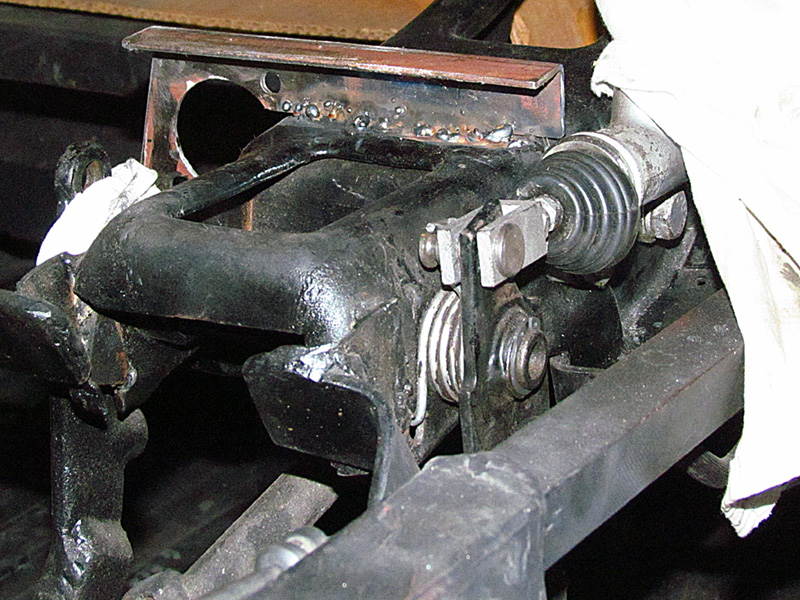
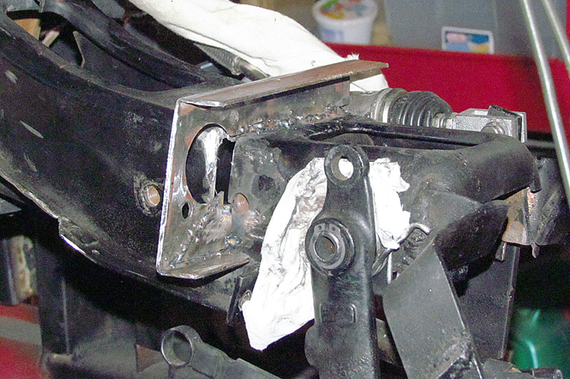
Then I moved on to the pedal bracket.
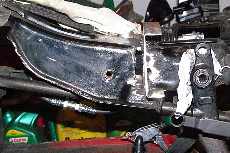
After much measuring and cogitating, I decided to cut out and reposition the pedal bracket back 1" and down 1".
I want to solve two problems: first, to move the pedals closer to the driver;
and second, to drop it an inch to give greater clearance between the master cylinder and the hood panel.
That will also give more height difference between the clutch and brake cylinder and the reservoir.
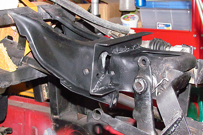
Once I cut the bracket free, then I had to make a new framing to hold the bracket in its now location.
That also meant that I would need to do my own welding - or learn how to do it.
I laid out new framing to weld the bracket to.
But when I began welding the bracket in place, my framing welds started breaking loose.
It was a frustrating day grinding down welds and trying again and again.
The next day, I tried increasing the heat setting and got good welds.
I now understand a bit more about welding.
I still need to position the throttle and then run the throttle cable, AND THEN I CAN START THE ENGINE . . .
next year.
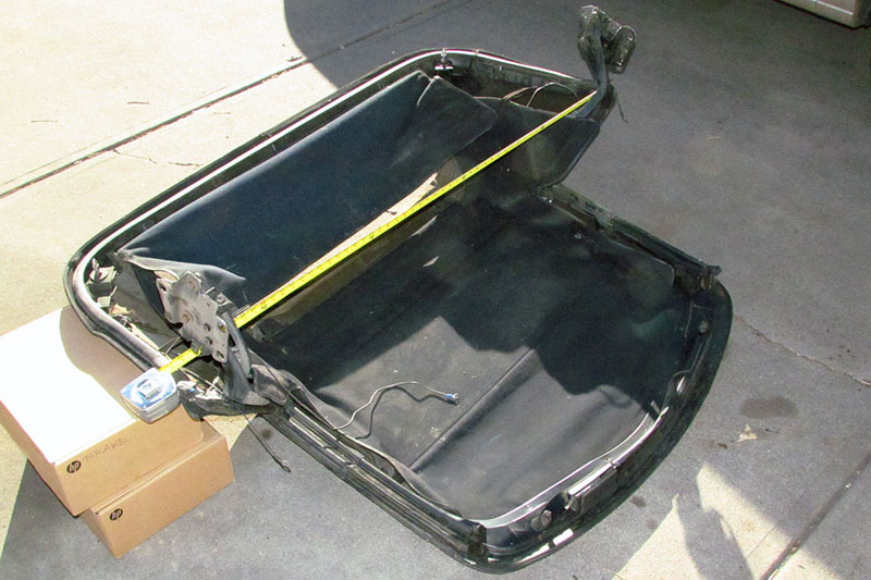
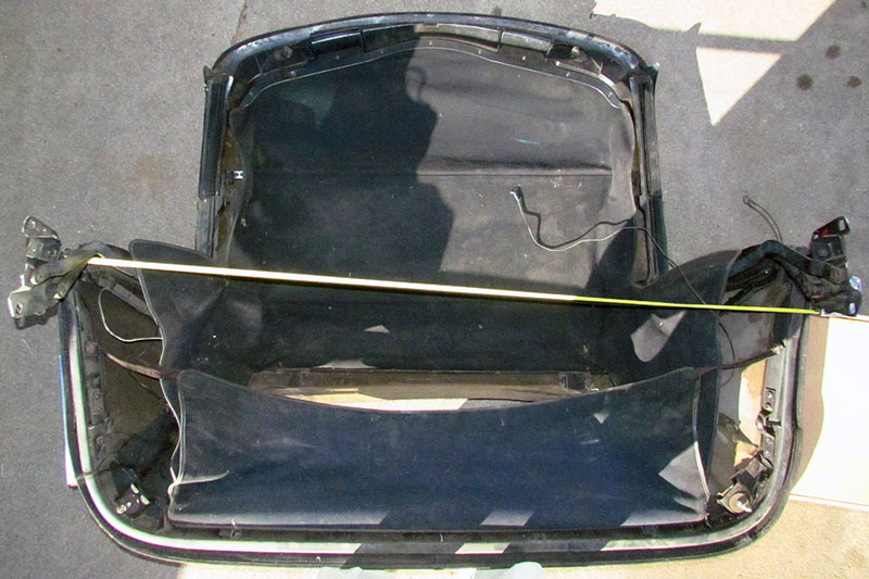
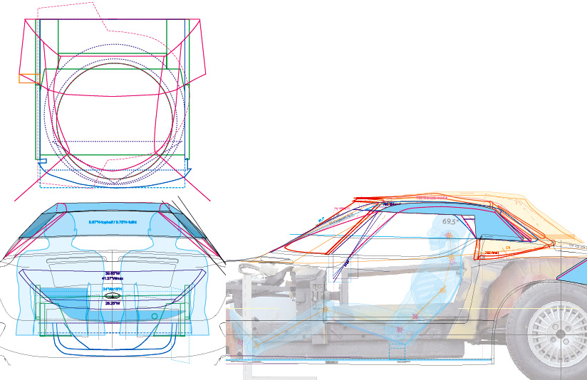
With the temperatures still in the 50s, I pulled out the C4 soft top I intend to use and opened it and measured it.
Very unhappily, it is between 1/4 to 1/3 larger than I thought.
I will have to cut every piece, being careful to allow it to (un)fold.
I have to admit that it's unreasonable to do all that.
And I cannot find other alternatives close enough to what's needed for the Monza.
So the althernative is to design a removable hard top.
There are advantages to it - it should be lighter and stronger.
But the big problem is how to make it so it can fit in the car when not used.
So I go back to my line drawing and begin drawing up variations.
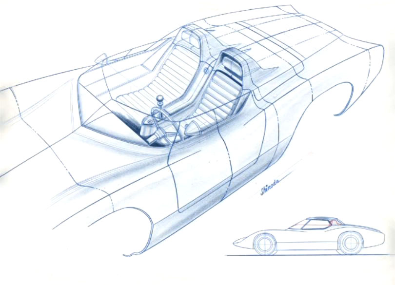
I have three images of the production Monza that was never approved for production but whose design went to roller full-size model.
One drawing shows Larry Shinoda's idea for a hard top!
But even those are too large for my chassis, so I am working on trimming dimensions and considering folding parts.
It's a work in progess.
next year.
Check out 2021 for more progress!
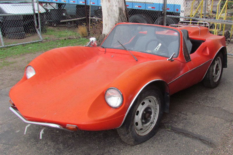
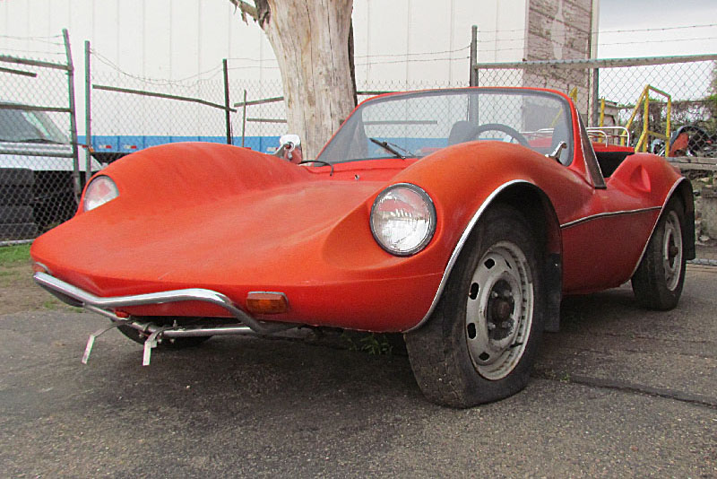
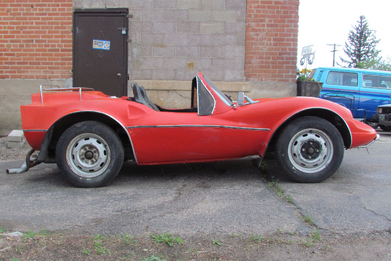
The Build--2020
January
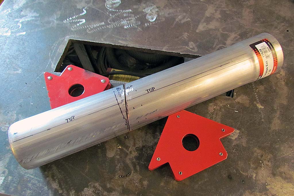

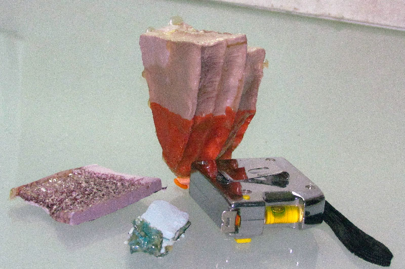
(L) The cut on the 3" exhaust pipe to make the first bend
(CL) The cut positioned for welding
(CR) My first real weld - ugly . . . but it holds. It takes more time to grind down than to weld.
(R) The master cylinder set up in the vice to test if it can pump brake fluid. Fluid goes in hoses using funnel, gets pumped by pedal rod,
and comes out brake lines into yogurt container. Cinch!
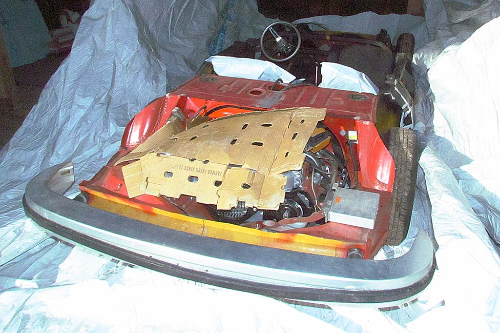
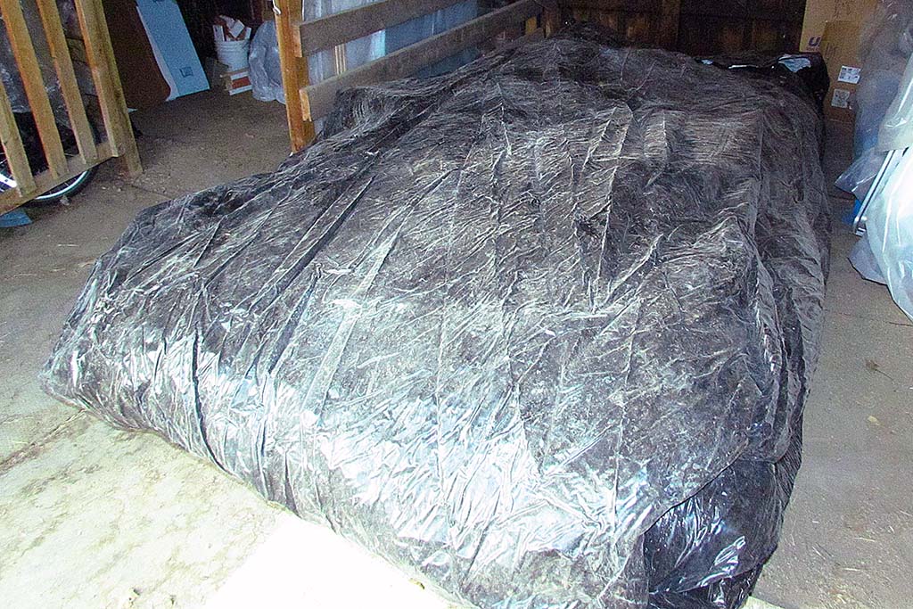
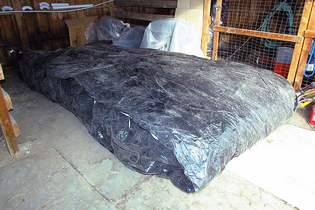
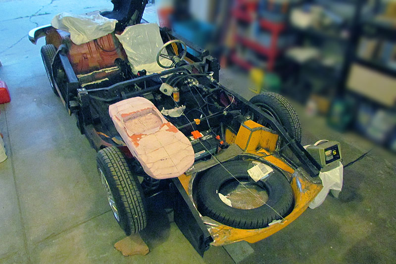
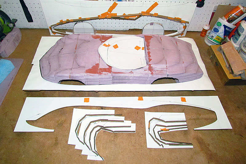
(L) The chassis before laying the first tarp over the top and before enveloping it with the grain bag plastic
(C) After about an hour of pulling taunt and trimming excess plastic, here it is enfolded by the grain bag plastic.
Note that black side is out. For grain it is inside, but there was still residual wheat seeds on it and I did not want to attract mice inside.
(R) A view from the left rear
February
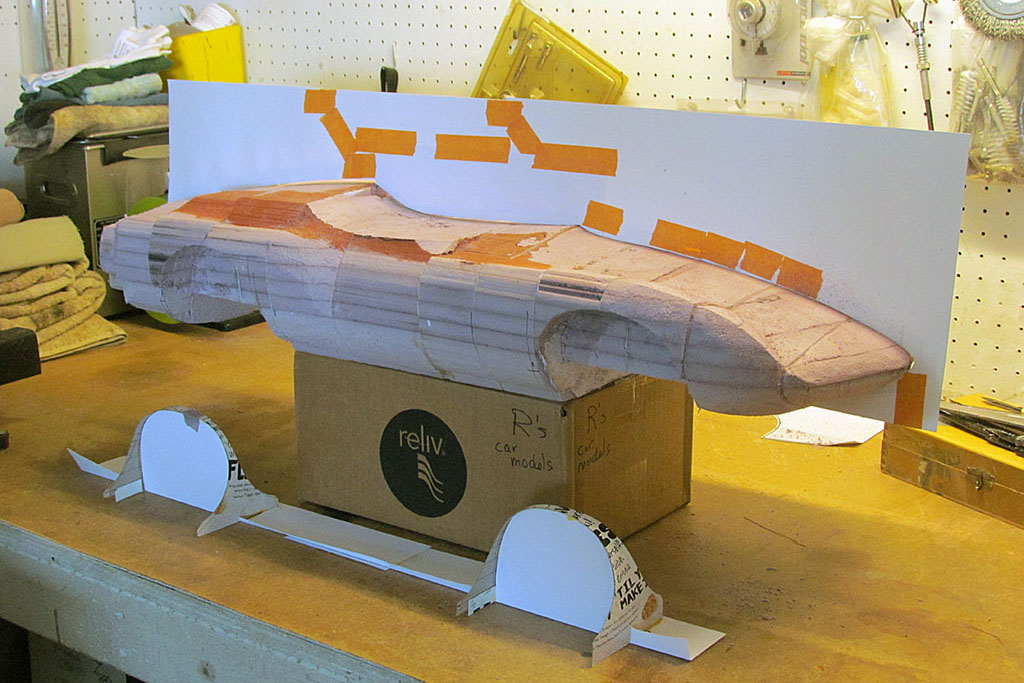
1st ROW
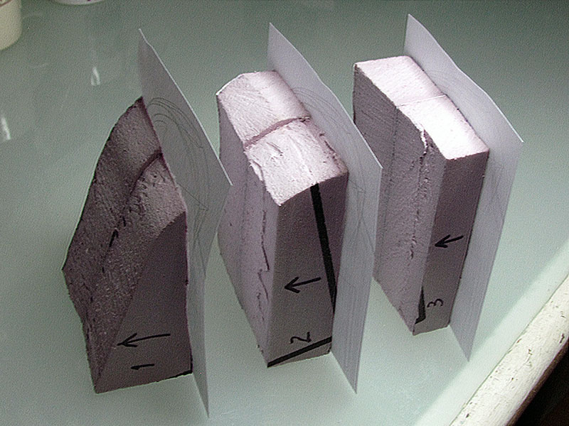
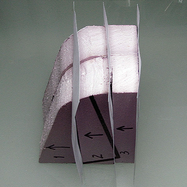
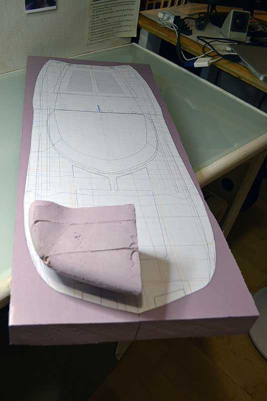
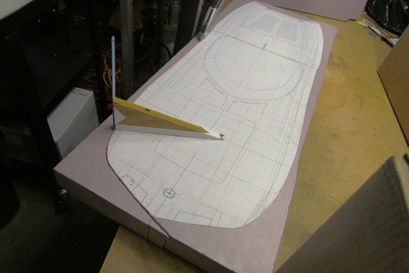
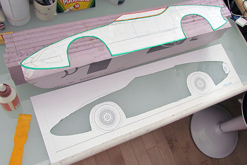
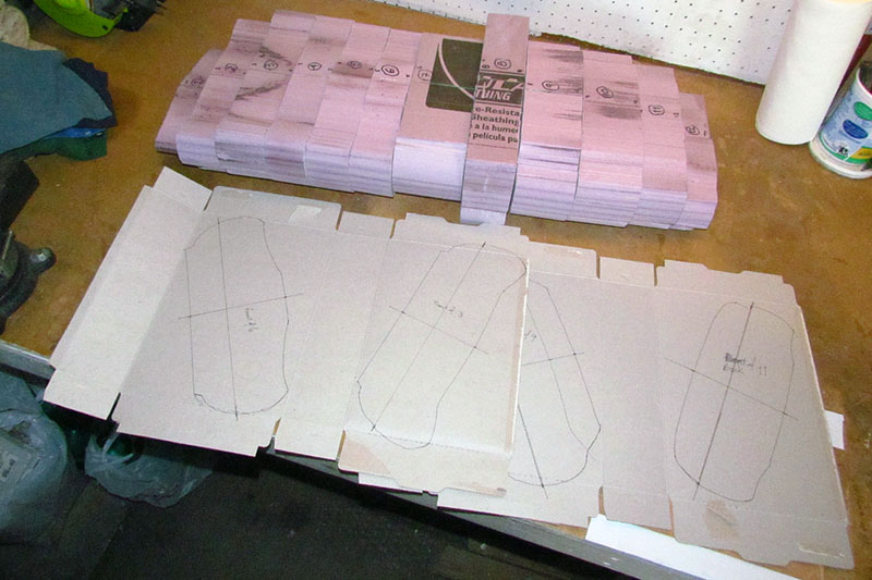
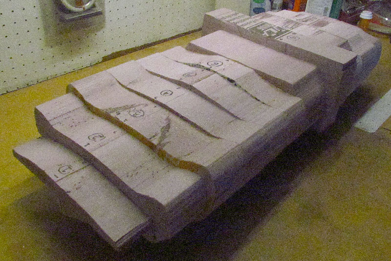
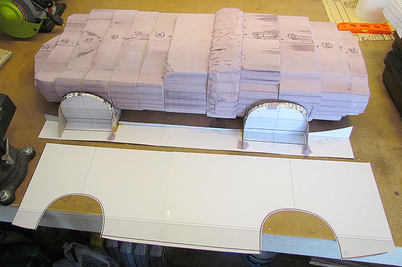
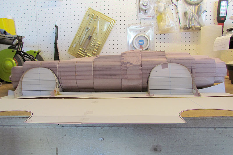
(L) Making the test shape - I already cut out the top view shape, sectioned it, and glued the contour printouts onto the sections.
(C) The sections are placed together for fit before cutting the contours.
(R) Here the contours are cut out and the sections are glued back together.
2nd ROW
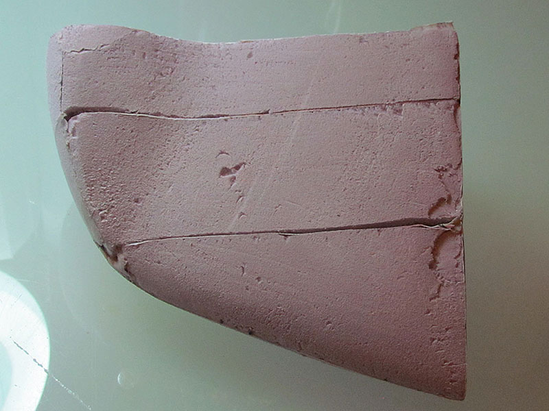
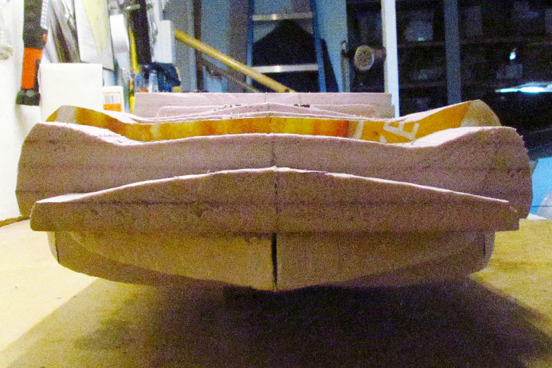
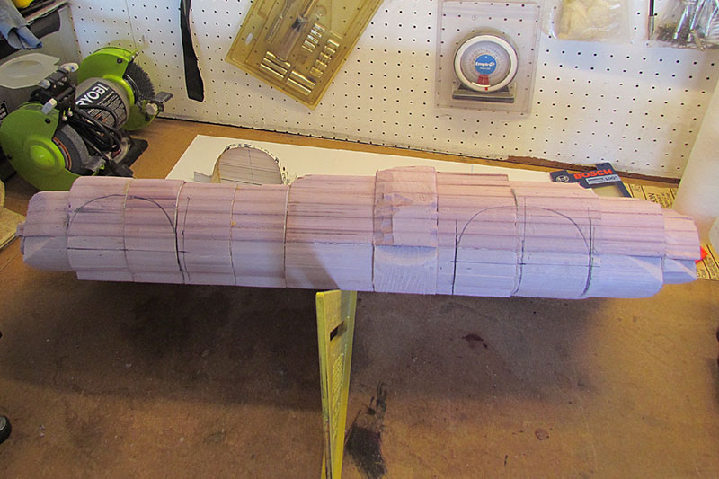
(L) After sanding with 100 grit and studying photos as I went, I arrived at the right corner shape of the nose.
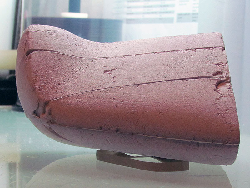
(C) Here is a top-down view
(R) And a front-on view.
3rd ROW
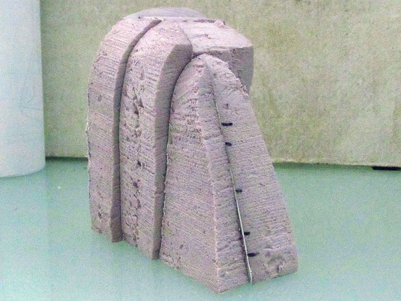
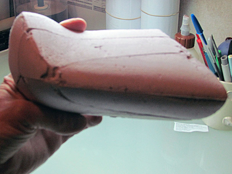
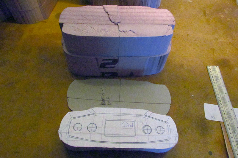
(L) My hand gives an idea of size. This is 1/5 scale.
(C) The shape rests in position on top of the lower body foam piece, which has the top-down contours glued onto it.
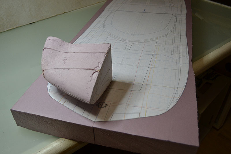
(R) And another similar view. I show a stereo view from this angle in the March photos.
March

1st ROW
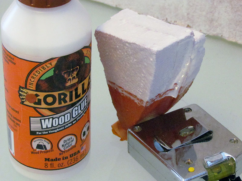
(L1) I did a quick test of simple coatings over the foam to learn if they could resist fiberglass resin. I tried latex house paint and wood glue. Even the overlap of the two could not resist the melting effect of the resin
(L2) See what I mean?! The two pieces lying down are resin on untreated insulation foam; pink on left, blue in the middle.
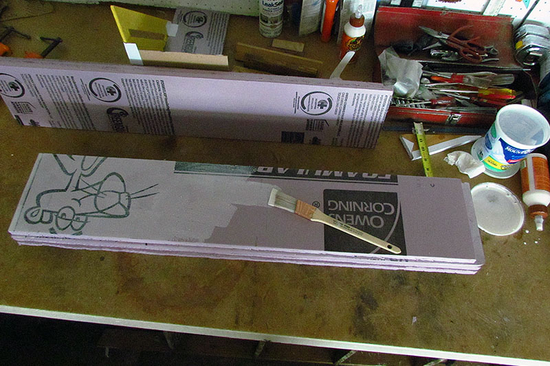
(C) Adopting a suggestion from a friend, I decide to use 1/2" layers of foam for the above-beltline body, hoping it will help me sand to shape more symmetrically left to right. the idea is that I can use the break lines between layers as contour lines.
(R) It is hard to see, but I am glueing back together the left and right halves of the below-beltline foam block. It is only tacked together, because I will break it apart to add a contour drawing. I will do this for every 1/2" layer, too.
2nd ROW
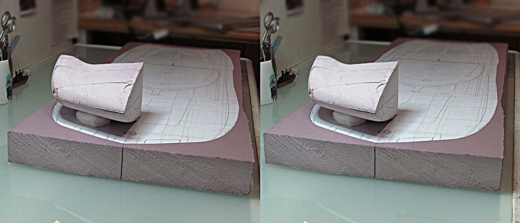
(L) Here is a stereo 3-D view of the below-beltline foam bloack with the top-down contour drawing, and with the nose test shape in position above it.
(C) Here is how I cut out the contour using just a hacksaw blade. The wood triangular block helps me keep the blade vertical as I cut.
(R) And the result. It is still winter out and snow is about. So it looked like a boogie board or a snow board. So I dressed to look the part. "Time to shred those slopes!"
April-May
1st ROW
(L) I begin glueing up the 1/2" layers for the foam above the beltline. I am hoping the lines between the layers will help me sand symmetrically left to right. I sure hope so, or its a lot of unnecessary work!
(C) The upper half-inch layers are now one block and I glue it to the 2-inch lower block to reconstitute the foam block for the body.
2nd ROW
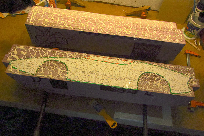
(L) Recall that I purposely cut the block in half lengthwise. I trace around the negative shape of the body side profile with a black marker. I hope this will clue me when I sand down to it.
(C) Next I glue the positve shape of the body side profile to one of the half blocks.
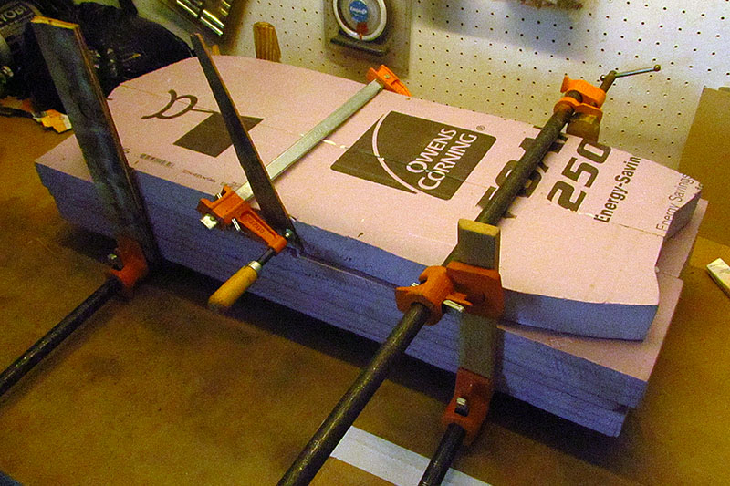
(R) Preparing to glue the two halves together, this show how much undiluted glue I used. It was more than enough.
3rd ROW
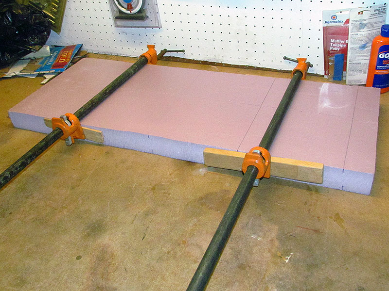
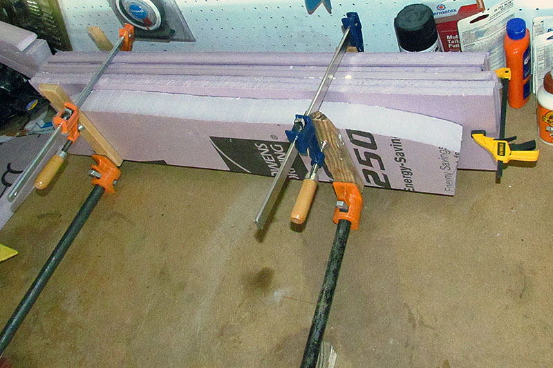
(L) I then clamped the two halves together to dry. As it sat on my table, the glue dripped out in puddles for more than a week.
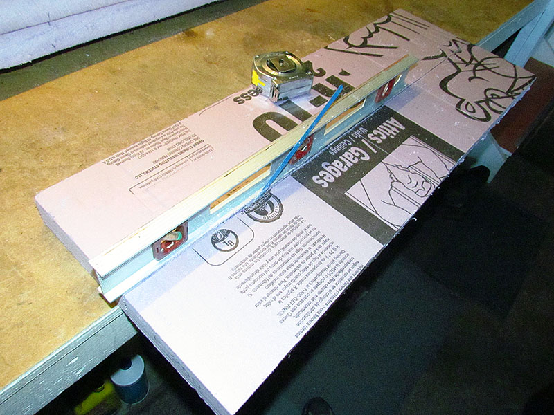
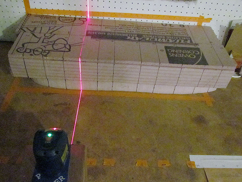
(C) Finally it was dry. Then I laid out my section cuts. Since the different layers were not equal dimensions, I compensated by using a laser level. It worked, though not always perfectly.
(R) And then I cut each section. This shows the first cut at the nose. All done with a hacksaw blade in gloved hand. Each cut lost about the thickness of the chipboard cardboard like a cereal box.
4th ROW
(L) I then glued an index card contour on each section.
Note that I glued them onto the rear of the sections for the front half and the front of the sections fro the back half.
(C) They are not ready to be glued together yet! I still need to cut out the contours on a scroll saw.
1st ROW
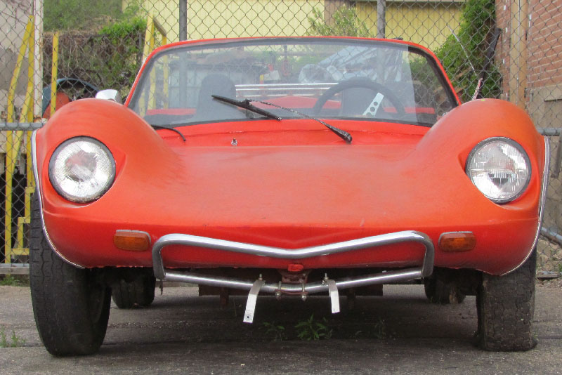
(L) It was a shock to glimpse this out of the corner of my eye as I drove by Pat's VW. THAT LOOKS LIKE A MONZA!! I stopped to examine it.
(C) It is obviously an old dunebuggy body, although it looks to be on a full-size Beetle chassis. The windshield could be from a late model Beetle or SuperBeetle.
(R) It was quickly apparent that it did not resemble at all the Monza SS, but that front end and fenders echoed it just the same.
2nd ROW
(L) I have never seen a photo of this dunebuggy body before. It was after hours so I could not ask. An internet search reveals it to be a Vakaro, a rare body.
(C) The rear hump between the rear fenderline looks boxy and even grotesque for proportions.
(R) Otherwise, this might have been a snazzy little sports car in its day - or even now. But this one is old and weatherbeaten. After a week, it was parked in the fenced yard next to the shop. I will have to stop in and get the scoop from Pat.
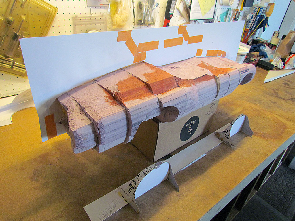
June
1st ROW
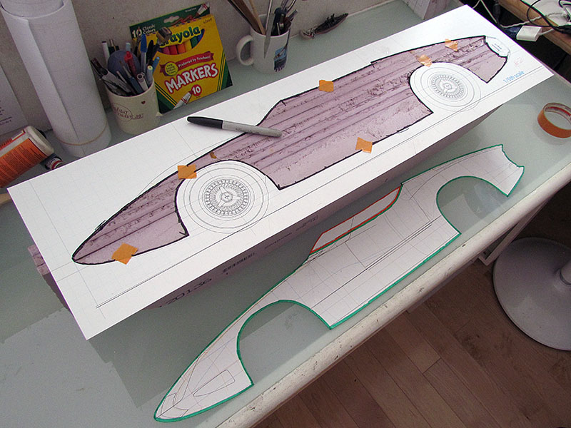
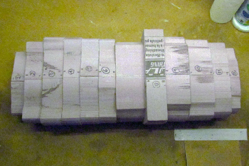
(L) I traced the four contour sections onto the chipboard.
(C) I cut them out inside the contour line so that when glued, it will not protrude from the foam. I don't want to have to sand it or trim it. But it turned out I still had to because I did not account for the contour on the back side and how it might expose some of the spacer.
2nd ROW
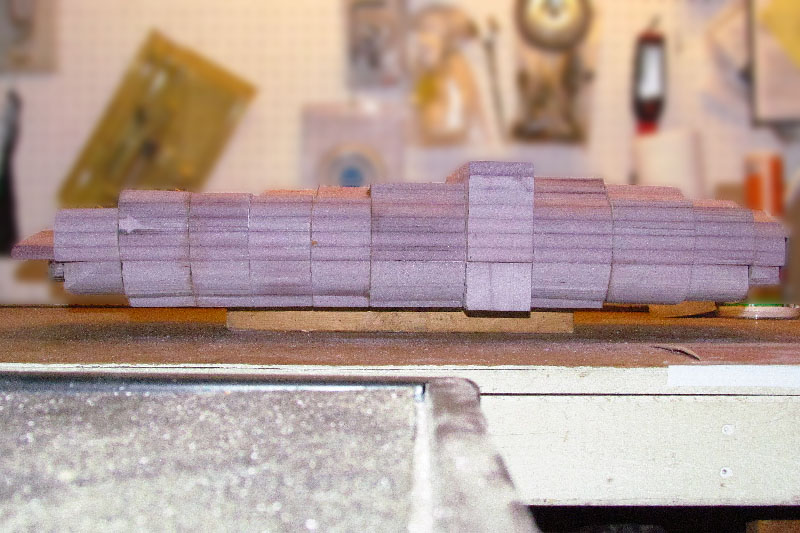
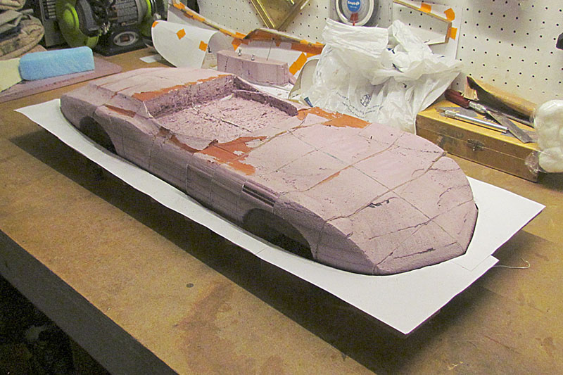
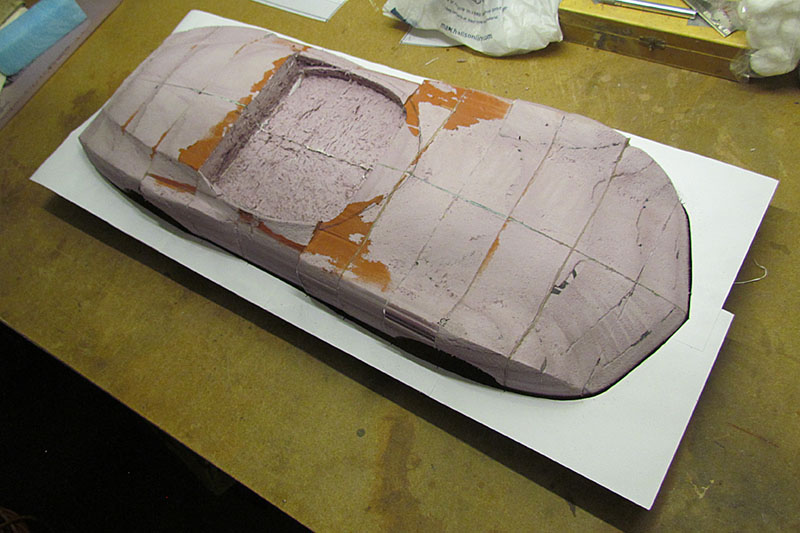
(L) Top view of the glued-together model
(C) 3/4 front view
(R) Head-on view. I am not concerned much with visible gaps. They will get filled at some point.
3rd ROW
(L) Driver-side view
(C) 2/4 rear view, showing the Kamm cove cutout
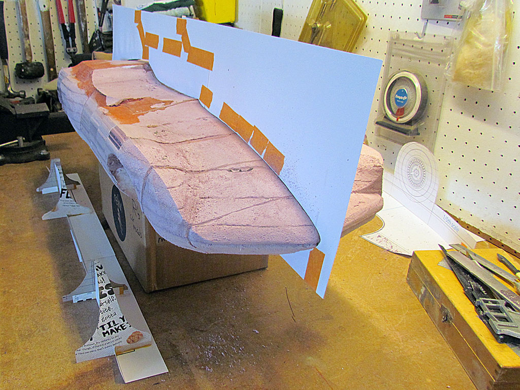
July
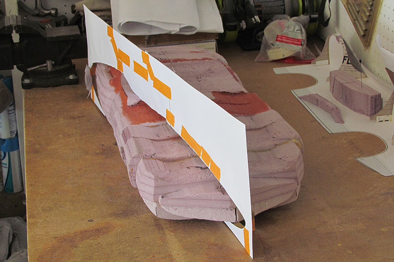
1st ROW
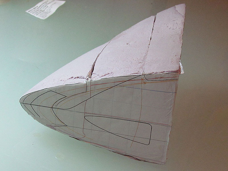
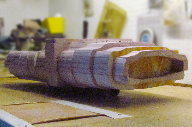
(L) I decided to cut out the wheel wells before carving further. I created a template for each well to follow the body shape, plotting it our in Illustrator.
(C) It aligned pretty closely to the section templates.
(R) It then was a simple matter to trace the outline onto the foam and carve the wells away.
2nd ROW
(L) Before proceeding further again, I created a centerline template, which is the highest point on the model except for the front fenders. Once the shape fit within the template, I knew where to begin from.
(C) It does not have to match it exactly. In fact, it should fit within with space to spare because I will coat the foam with a hard final surface.
(R) The fenders are still not tightly defined.
3rd ROW
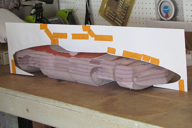
(L) But it is looking like the car.
(C) The cockpit is set to the sill of the windshield. I will do the glass at the end.
(R) Another view.
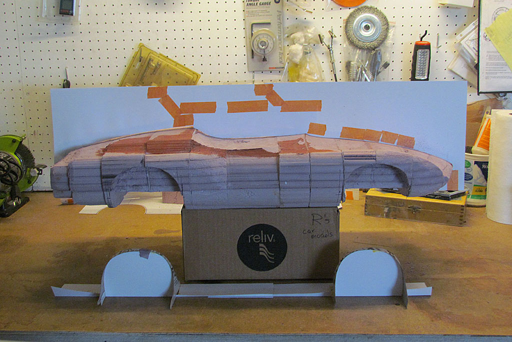
4th ROW
(L) Next I made a top-view contour template. I have carved into the cockpit to define it, keeping the dashboard.
(C) Note how the foam layers are showing up and helping keep contours symetrical
(R) The widest point varies in height along the length of the car.
August-September
1st ROW
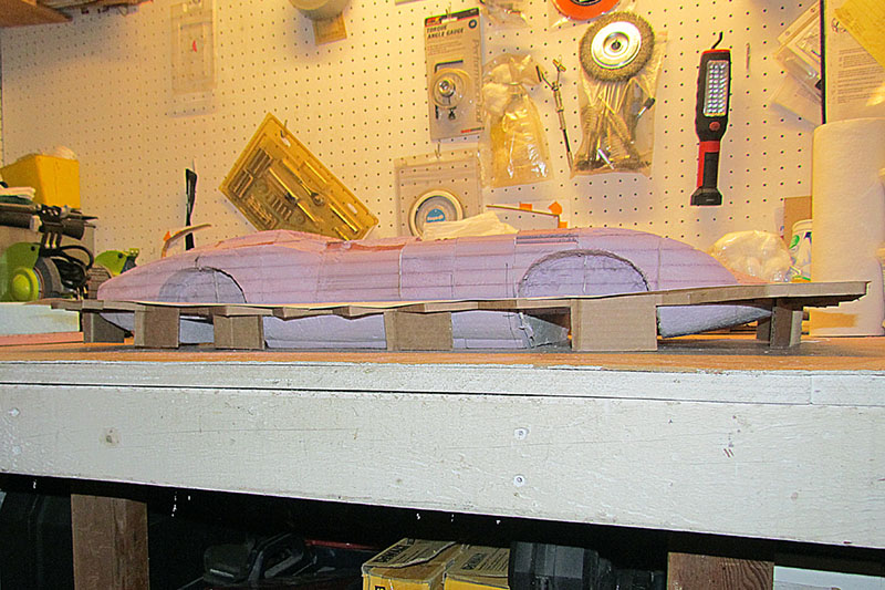
(L) I brought the chassis back to the garage to get it to run. Here is the model on it for orientation.
(C) First up is getting the brakes to work again.
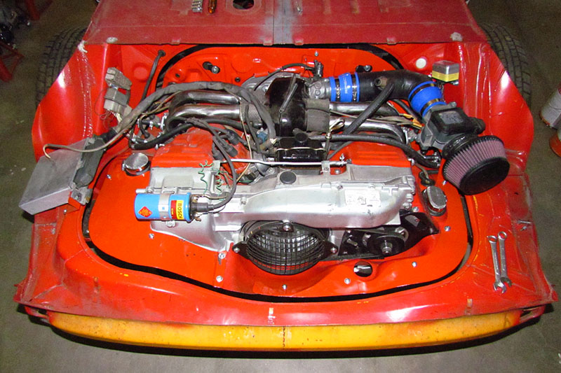
(R) Second up is to get the injector meter connected to the throttle body. I need to place it beside the engine and need a pipe between the two components. Here I am laying out my cut like I did before.
2nd ROW
(L) The assembled pipe, meter, and filter plus the cardboard pattern for the mounting bracket. Which led to the next task, fixing the tin it will mount on, which had too large a gap.
(C) The left-hand pattern is fitted in place and brown paper is taped down on the left side and outlines are pencilled on it.
(R) The brown paper is spraymented onto chipboard and trimmed out. Here is has been positioned, trimmed, and adjusted to fit allowing a 5/8" to 3/4" gap.
3rd ROW
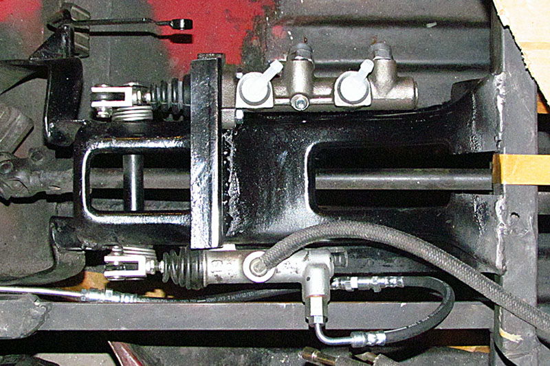
(L) The new, large-bore, SuperBeetle master cylinder arrived. Now to fit it. Another pattern is made of the mounting surface, transferred to a pattern to fit the pedal bracket, and used to cut out this U-channel.
(C) A 3/4 view from the passenger front side. The welds still aren't pretty, but I did it all by myself.
(R) Side view. I had to cut out a notch from the pedal bracket to fit in a corner of the mounting collar of the master cylinder.
4th ROW
(L) Quickly primed with rust protector.
(C) The new master cylinder in place.
(R) Top view. Discovered that new brake lines are needed. It takes a different thread from the 412 into the cylinder.
October-November

1st ROW
(L) I completed a set of contour templates for when I return to the model.
2nd ROW
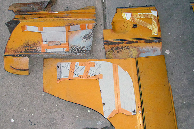
(L) Tin patterns laid out on VW 412 sheet metal.
(C) The cutout tin pieces in place.
(R) And after being painted and with the MAF and computer box in place.
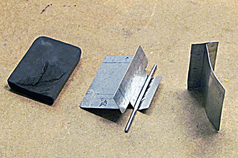
3rd ROW
(L) A trial piece. The rubber piece is a filler/damper. The metal rod is to fit in place of the original flap that I did not have in order to hold the plug in place.
(C) The plug in place between the fan housing (L) and heater box (R).
(R)The same with the heat wrap over it.
4th ROW
(L) The engine bay with muffler added.
(C) A look-down view of the same.
December
1st ROW
(L) The relocated pedal bracket and its framing, driver side view.
(C) 3/4 view from the passenger side. I intend to keep the reservoir in the center in front of the dash, which is the highest location on the front.
(R) An early weld of mine (L) and a good weld done by my neighbor (R). Acceptable IF it holds!
2nd ROW
(L) C4 convertible top opened seen from rear.
(C) The top from a 3/4 view.
(R) A nearly straight-down view. Every single bow would have to be cut and the joints recalculated. I don't trust my ability to do that accurately enough.
3rd ROW
(L) Larry Shinoda's XP782 sketch with a removable hard top.
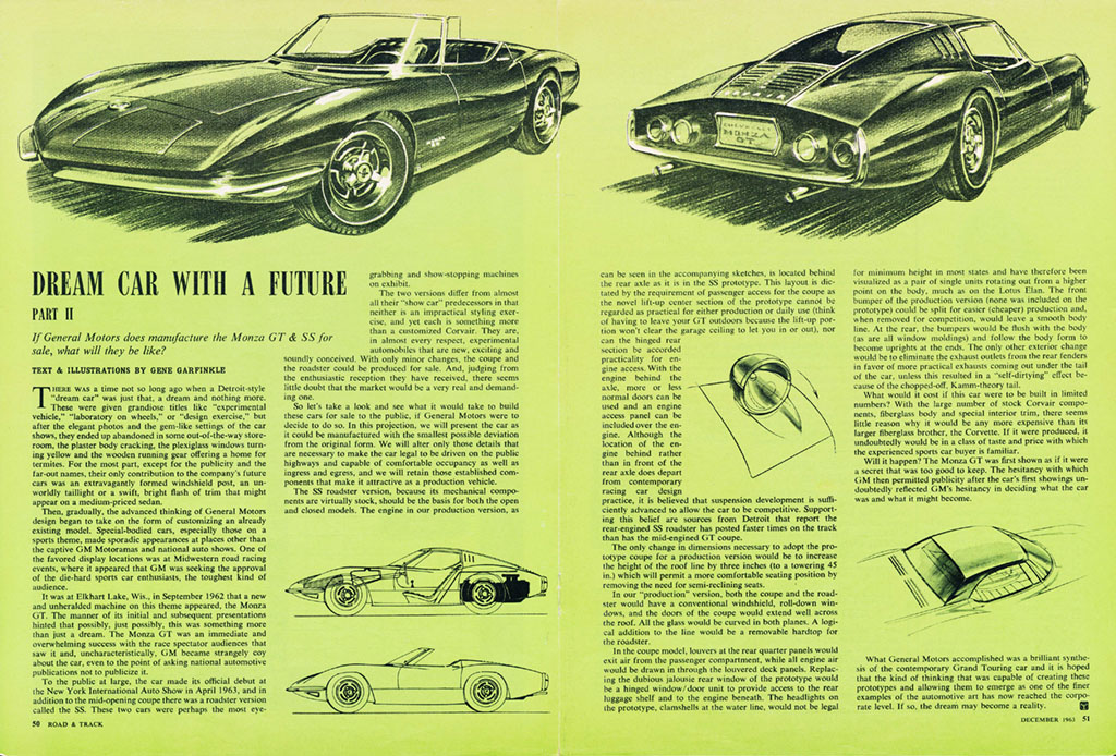
(C) A Road & Track article from Dec. '63 showing a good representation of the production Monzas.
(R) Screen cap showing my hardtop in light blue (adapted from the Shinoda drawing), the XP782 softtop in red line, and the C4 softtop in light orange. The C4 turned out much larger than I estimated trying to take dimensions from photos on an earlier attempt. Even so, it looks like a removable hardtop will also have to be collapsable to get it to fit the available space in the chassis.